Hey all! As my first ever design and build I am finally in the test box stage and got some measurements yesterday.
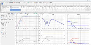
* Thick Blue/yellow line is my measured speaker response
** Orange is actual Markaudio CHR70 manufacturer response
*** Black line is my enclosure simulation from VirtuixCAD
1. Is it normal for simulated low end response be this far off from actual real world measurements?
2. Not worried too much about 100hz to 500hz as I am planning on implementing baffle correction via passive or DSP
3. Any suggestions on what might be causing exaggerated spike/dip around 1500hz and what can be done?
4. Spike above 10khz is tracking manufacturers response almost one to one... do people typically leave it as it is with fullrange build?
Overall I am pretty satisfied with my first try, spent a lot of time simulating this box. Looking for suggestions for improvements and general feedback. Thank you all!


- Fullrange Markaudio CHR70
- Around 9.8L box with front facing slatted port and some fluffy stuffing and damping lining
- Box/Port FB: 51.2 Hz
- F3: 49 Hz
- Port length 9"
- Port area 5"
* Thick Blue/yellow line is my measured speaker response
** Orange is actual Markaudio CHR70 manufacturer response
*** Black line is my enclosure simulation from VirtuixCAD
1. Is it normal for simulated low end response be this far off from actual real world measurements?
2. Not worried too much about 100hz to 500hz as I am planning on implementing baffle correction via passive or DSP
3. Any suggestions on what might be causing exaggerated spike/dip around 1500hz and what can be done?
4. Spike above 10khz is tracking manufacturers response almost one to one... do people typically leave it as it is with fullrange build?
Overall I am pretty satisfied with my first try, spent a lot of time simulating this box. Looking for suggestions for improvements and general feedback. Thank you all!
If i use your numbers, and assume that given you have a round-over, the effective length is 8.5” i get this sim. Is that what you simmed?

Also note that while useful in figuring out your alignment F3 is meaningless to humans (ref Toole), better to use F10 (low 40s), and F6 (high 40s)
dave
Also note that while useful in figuring out your alignment F3 is meaningless to humans (ref Toole), better to use F10 (low 40s), and F6 (high 40s)
dave

It's 0110 here, so I only have a minute before attempting to get some sleep (unlikely, but you never know your luck). Re the ~1.1Khz - 2.1KHz region, probably some edge diffraction; it's in the right region & the characteristics are fairly typical. For the LF -it could be a number of things; an impedance plot would help narrow it down.
Thank you for your time sir! I will be measuring impedance in the next couple of days and will post here. Good night!It's 0110 here, so I only have a minute before attempting to get some sleep (unlikely, but you never know your luck). Re the ~1.1Khz - 2.1KHz region, probably some edge diffraction; it's in the right region & the characteristics are fairly typical. For the LF -it could be a number of things; an impedance plot would help narrow it down.
Close, port length is 9"
So 9.5” if you measure from the start of the roundovers? Not that it makes a big difference with the sim.
dave
1. Depends on which software used, how measured.1. Is it normal for simulated low end response be this far off from actual real world measurements?
3. Any suggestions on what might be causing exaggerated spike/dip around 1500hz and what can be done?
3. Hmm, driver centered at ~13543/2/4 = ~1693 Hz dip, 5.5 = ~ 1231 Hz, so summed = ~ sqrt(1231*1693) = 1444 Hz center frequency dip and why off center and dims not close to each other is recommended, so ideally need some baffle face damping and/or diffraction devices tacked on.
- Is this what you mean by “baffle step damping”? See photoclose to each other is recommended, so ideally need some baffle face damping and/or diffraction devices tacked on
- what are you referring to as far as the “diffraction devices tacked on”?
Attachments
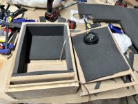
a reflex usually has no damping fill, loose the whit stuff, and i would use something other than the foam, it does not work well.
What would you suggest to use instead of foam?reflex usually has no damping fill, loose the whit stuff, and i would use something other than the foam, it does not work well.
I prefer natural felts, i use recycled cotton (often sold as sound and heat insulting blankets for things like water heaters and such. Wool felt works well too, i have used a lot of that recycled over old boxes.
dave
dave
Home Depot used to carry the recycled Denim insulation. If you've got a store close by, it's worth checking out. It's probably going to be too thick, so try and separate into thinner layers if you find some.What would you suggest to use instead of foam?
jeff
Last edited:
Hello1. Is it normal for simulated low end response be this far off from actual real world measurements?
2. ...
3. Any suggestions on what might be causing exaggerated spike/dip around 1500hz and what can be done?
4. Spike above 10khz is tracking manufacturers response almost one to one... do people typically leave it as it is with fullrange build?
View attachment 1152518
nice work !
some answers / impressions
1) yes - if you measure direct very close to the membran. Repeart measurement at the usually notetd 1m distance oder minimum at baffle width distance.
2)...
3) may be artefact from measurement so close
4) had that driver for a longer time without care to the peak above 10kHz.
- Home
- Loudspeakers
- Full Range
- 9.8L Markaudio CHR70 Fullrange first speaker design & build questions