Hi everyone,
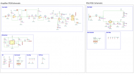
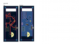
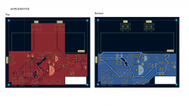
I'm redesigning a 5w LM1875 Guitar Power Amplifier that's powered by a Line 6 Helix (Line Level out) as the preamp. Is someone able to have a look over these images and let me know if there are any glaring errors they can see in either the PCB layout or the Schematics? The PSU board is powered by a LRS-36-100 SMPS.
Ive got a version of it already working, but this has had a few major changes from the first design, so before i send for it to be made,I thought I'd ask around get get a few sets of eyes looking over it.
ps. On the PSU board, I have both Audio and Power ground coming back to the same star grounding point on the pins. If that ok to do or should it be tackled differently?
Thanks!
Attachments
Checking pastel details makes sore eyes.eyes looking over it
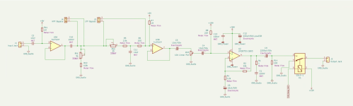
C2 is backward and way too big (0.017Hz). Use another of C11, 10nF, and you don't need polarity.
What is the DC voltage on the filter network between U3A and U3B? Zero or plus six? I think R10 can return to +6 BUT you want a big bypass cap on that reference voltage! (Minimum the 10uFd you took out at C2, but 47 and 100u are popular.) Then R7 is not needed, U3B gets bias from U3A.
The LM1875 datasheet suggests 22k where you have R8 1Meg. This is because the input bias current can be a couple microamps. In 1Meg this makes a couple volts off-center. Perhaps not critical for a G-amp, but I don't see a reason.
The output relay should ground the jack (not the power amp!). Or just break the connection, no ground needed.
You have total voltage gain of 15 for input sensitivity of 800mV. G-amp sensitivity is usually 50mV to 10mV. Are you sure this is good?

Thanks @PRR,
1) Yup, Stupid oversight. That electrolytic is now a non polarised 10nf
2) With the reference voltages would it work if I were to bring the C10 cap before that bypass switch? That was its always going to be at 0 before the rebiasing? I say this because whenever the HFP isn't bypassed, it's going to block the DC, so I might as well make it permanently blocked and then rebiased at the end?
3) Changed to 22K Thanks!
4) Happy to be completely wrong (And assuming I am). When the relay is flipped like you've illustrated, doesn't that mean the C9 output cap isn't grounded before the mute circuit delay is activated and cant get itself up to 1/2 VCC leading to speaker thump once the relay fires?
5) There's a preamp before this, so it's putting out a larger signal than a guitar on its own. Seems to be plenty loud in the current iteration. 🙂
Thanks for the help so far.