I'm redoing an amplifier I built a few years ago using the same circuit using new parts (caps,sockets,enclosure,OT) I found diylayout creator and I'm hoping for a little critique.
I also now realize that nothing is drawn to scale and it might not fit. Lol It's 12x8

.jpg")
I'm a little fuzzy as to were the ground the dual .1uf feedback capacitors. Is it part of the small signal section that goes to the - cap on the 255v? Or is it part of the( -)in the B+ 265v section?
I also now realize that nothing is drawn to scale and it might not fit. Lol It's 12x8
I'm a little fuzzy as to were the ground the dual .1uf feedback capacitors. Is it part of the small signal section that goes to the - cap on the 255v? Or is it part of the( -)in the B+ 265v section?
Last edited by a moderator:
I'm basing the ground design on a semi star in that each section power/signal ground is returned to the base of filter cap serving that section. Keep the noisy end away from the small signal. Transformer HV center tap goes to the start of the bus on the first filter cap.
ttps://www.aikenamps.com/index.php/grounding
And the valve wizard guided me a little.

I'm not sure about isolating the ground buss from the chassis. Right now I have it tied to chassis at the input RCA jack.

ttps://www.aikenamps.com/index.php/grounding
And the valve wizard guided me a little.
I'm not sure about isolating the ground buss from the chassis. Right now I have it tied to chassis at the input RCA jack.
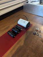
After some advice I've changed my design to incorporate terminal strips vs turret lugs. (Keep it simple)

The parts are mostly gathered besides hardware and a few 5 watt resistors that I might need to drop b+ a few volts.

The marks on the enclosure are from when I was trying to figure out a turret board.
(What removes sharpie from aluminum? lol)

I do have a few questions about replacing the 5y3 rectifier with an indirectly heated variety and I'm not sure were to look and if my filament supply will work with anything else.
The parts are mostly gathered besides hardware and a few 5 watt resistors that I might need to drop b+ a few volts.
The marks on the enclosure are from when I was trying to figure out a turret board.
(What removes sharpie from aluminum? lol)
I do have a few questions about replacing the 5y3 rectifier with an indirectly heated variety and I'm not sure were to look and if my filament supply will work with anything else.

If you mean the 0.1uF cap in the series'd RC drawn directly above the OPT, that's a Zobel and wants to be directly across the OPT secondary, but it's not critical.
The type 5Y3 has a 2A filament, so can be replaced with either the 5V4 type or the 5AR4/GZ34 type. Take B+ from pin 8 and don't use any socket pins for tie points. You will have a somewhat larger B+ voltage with either type.
All good fortune,
Chris
The type 5Y3 has a 2A filament, so can be replaced with either the 5V4 type or the 5AR4/GZ34 type. Take B+ from pin 8 and don't use any socket pins for tie points. You will have a somewhat larger B+ voltage with either type.
All good fortune,
Chris
6CA4 is the only rectifier shown on the schematics and drawings of the first 6 posts in this thread.
The 6CA4 has a cathode that is isolated from the filament, the cathode can be up to 500 volts higher than the filament voltage.
That allows you to use the 6.3V to run the input/driver tube, output tube, and the rectifier tube (all run from the same 6.3V filament secondary).
If you trust the 6CA4, and if it is of good quality . . . OK
If the filament to cathode insulation of the 6CA4 goes bad, there will be some real burnout of one or more components.
The other rectifiers listed in this thread, 5Y3, 5V4, 5AR4/GZ34 are totally different than the 6CA4.
Their filaments are 5V, and the filaments are at B+ (high voltage output), and the 5AR4/GZ34 has a cathode that is connected to the filament.
That means they need their own 5V filament secondary.
You can not power input/driver or output tube filaments on the same 5V secondary winding as the 5V filament rectifier (not even if they are 5V filament tubes).
The last few remaining parts arrived. (100 ohm locking pots, fr4 board, switch craft jack, isolating washers, terminal strips and a few 5 watt resistors for the headphone attenuator circuit. Sweet!

I can't believe the high quality of the parts from tube depot and digikey. I usually use whatever I can find on Amazon or salvage from thrift finds.
Beautiful dual row terminal strips. ( I Bought a variety plus the price was cheaper then expected) I really hope my soldering skills will suffice..

Finding a 50 ohm 3 watt pot was difficult. I stumbled onto these on digikey and I'm surprised at the machining quality.
(NTN electronics)

This is supposed to be a simple circuit yet my enclosure is filling up quickly. I'm using tiny OTs too!

I can't believe the high quality of the parts from tube depot and digikey. I usually use whatever I can find on Amazon or salvage from thrift finds.
Beautiful dual row terminal strips. ( I Bought a variety plus the price was cheaper then expected) I really hope my soldering skills will suffice..
Finding a 50 ohm 3 watt pot was difficult. I stumbled onto these on digikey and I'm surprised at the machining quality.
(NTN electronics)
This is supposed to be a simple circuit yet my enclosure is filling up quickly. I'm using tiny OTs too!
Attachments
Last edited by a moderator:
6CA4 is the only rectifier shown on the schematics and drawings of the first 6 posts in this thread.
The 6CA4 has a cathode that is isolated from the filament, the cathode can be up to 500 volts higher than the filament voltage.
That allows you to use the 6.3V to run the input/driver tube, output tube, and the rectifier tube (all run from the same 6.3V filament secondary).
If you trust the 6CA4, and if it is of good quality . . . OK
If the filament to cathode insulation of the 6CA4 goes bad, there will be some real burnout of one or more components.
The other rectifiers listed in this thread, 5Y3, 5V4, 5AR4/GZ34 are totally different than the 6CA4.
Their filaments are 5V, and the filaments are at B+ (high voltage output), and the 5AR4/GZ34 has a cathode that is connected to the filament.
That means they need their own 5V filament secondary.
You can not power input/driver or output tube filaments on the same 5V secondary winding as the 5V filament rectifier (not even if they are 5V filament tubes).
Sorry I didn't explain further. I'm using a donor HT transformer and 5y3 rectifier that I salvaged from my first tube amp build.
That amp used the same setup/circuit using salvaged components from an RCA-rs-188 and hot glue. Lol 😆
(I got lucky. I didn't realize how dangerous the HV was and I tested nothing. It worked )
Now I'm redoing it with a broader knowledgebase and a much better component selection. My only issue is the 5y3. Id like to find a substitute that heats up more slowly with a similar voltage drop.
Thanks for the input 👍. Without it I'd probably be a little lost.
In this circuit it put out 290 at 100mah.
The new circuit calls for b+ 265 at around 100mah.
(I'm building a CLCRC in order to tame it)

If you want slow start, there are a couple of 5Y3 variants that are indirectly heated - the 6087 and the 6106.
If you have an extra Un-used 6.3V filament winding (that is not used by the other 6.3V tubes) . . .
Then try this:
Connect the 5Y3 filament and a 0.65 Ohm 10 Watt resistor in Series, and connect that series circuit across the extra Un-used 6.3V filament winding.
Connect one end of the filament to your first B+ filter part; (a capacitor?) (a choke?).
The cold 5Y3 filament is way less than 1 Ohm, so there is a slow start as the 5Y3 filament warms up (At power-up, about 1/2 of the 6.3V goes to the 5Y3, and about 1/2 of the 6.3V goes to the 0.65 Ohm resistor, until sometime later when the 5Y3 warms up and gets 5V, while the 0.65 Ohm gets 1.3V)
2A x 2.5 Ohms = 5V, a warmed up 5Y3 filament.
2A x 0.65 Ohms = 1.3 V across the resistor when the 5Y3 filament finally warms up.
No need to purchase another rectifier.
Nobody has ever reported to me that they used this (my) technique.
You can be the first to use it; and the first to report that it works very well.
That resistor trick should work well but make sure that power resistor is not touching or near anything! It will get hot for the start up then just be warm after. It will do what you want and save money, how often does that happen?
Id try the trick unfortunately I lack an extra heater line. Good news is that I has pointed me to the 5ar4 (thanks again !) it has the filament bridged to the cathode. Heats up like a indirectly heated version.

Unfortunately it has a much lower voltage drop.
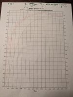
According to the above old diagram.
(How reliable are these numbers from the factory?)
My 5y3 put out 290 @100 b+
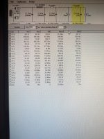
In psud2 I was able to duplicate these numbers using the same arrangement.
The 5ar4 shot up to nearly 360v with a ripple of 380mv b+ and 18mv to the preamp. (I think I'm reading that number right)
This allowed me to add another stage of filtering. A crazy CLCRCRC 33uf -1.5h-47uf-820r-33uf-820r-20uf and the
Voltages came right were I needed them.


The ripple voltage is now 19mv and less than 1mv. The 47ma across the first dropping resistor is a concern.
(I'm not good at math, but this points me to a 10 watt resistor correct? Lol)
This is welcome news because my headphone circuit will probably broadcast any hum.
Unfortunately it has a much lower voltage drop.
According to the above old diagram.
(How reliable are these numbers from the factory?)
My 5y3 put out 290 @100 b+
In psud2 I was able to duplicate these numbers using the same arrangement.
The 5ar4 shot up to nearly 360v with a ripple of 380mv b+ and 18mv to the preamp. (I think I'm reading that number right)
This allowed me to add another stage of filtering. A crazy CLCRCRC 33uf -1.5h-47uf-820r-33uf-820r-20uf and the
Voltages came right were I needed them.
The ripple voltage is now 19mv and less than 1mv. The 47ma across the first dropping resistor is a concern.
(I'm not good at math, but this points me to a 10 watt resistor correct? Lol)
This is welcome news because my headphone circuit will probably broadcast any hum.
Attachments
Last edited:
If you mean the 0.1uF cap in the series'd RC drawn directly above the OPT, that's a Zobel and wants to be directly across the OPT secondary, but it's not critical.
The type 5Y3 has a 2A filament, so can be replaced with either the 5V4 type or the 5AR4/GZ34 type. Take B+ from pin 8 and don't use any socket pins for tie points. You will have a somewhat larger B+ voltage with either type.
All good fortune,
Chris
6CA4 is the only rectifier shown on the schematics and drawings of the first 6 posts in this thread.
The 6CA4 has a cathode that is isolated from the filament, the cathode can be up to 500 volts higher than the filament voltage.
That allows you to use the 6.3V to run the input/driver tube, output tube, and the rectifier tube (all run from the same 6.3V filament secondary).
If you trust the 6CA4, and if it is of good quality . . . OK
If the filament to cathode insulation of the 6CA4 goes bad, there will be some real burnout of one or more components.
The other rectifiers listed in this thread, 5Y3, 5V4, 5AR4/GZ34 are totally different than the 6CA4.
Their filaments are 5V, and the filaments are at B+ (high voltage output), and the 5AR4/GZ34 has a cathode that is connected to the filament.
That means they need their own 5V filament secondary
You can not power input/driver or output tube filaments on the same 5V secondary winding as the 5V filament rectifier (not even if they are 5V filament tubes).
Thanks for the advice from my research they're not awfully expensive (5ar4) and I don't have to change the pin out.
The 6ca4 isn't what I originally ran with, I used the 5y3 . Now that I'm basically rebuilding the amp it opened up my options. The only thing I'm using again is the RCA trafo.
The 5AR4 does have considerably lower voltage drop so why not use one of the indirectly heated 5Y3 variants I suggested? The table I have says 5Y3 drops 60v, the 6087 drops 50v and the 6106 drops 60v.Id try the trick unfortunately I lack an extra heater line. Good news is that I has pointed me to the 5ar4 (thanks again !) it has the filament bridged to the cathode. Heats up like a indirectly heated version.
View attachment 1147039
Unfortunately it has a much lower voltage drop.
According to the above old diagram.
(How reliable are these numbers from the factory?)
My 5y3 put out 290 @100 b+
In psud2 I was able to duplicate these numbers using the same arrangement.
The 5ar4 shot up to nearly 360v with a ripple of 380mv b+ and 18mv to the preamp. (I think I'm reading that number right)
This allowed me to add another stage of filtering. A crazy CLCRCRC 33uf -1.5h-47uf-820r-33uf-820r-20uf and the
Voltages came right were I needed them.
View attachment 1147040View attachment 1147043
The ripple voltage is now 19mv and less than 1mv. The 47ma across the first dropping resistor is a concern.
(I'm not good at math, but this points me to a 10 watt resistor correct? Lol)
This is welcome news because my headphone circuit will probably broadcast any hum.
As far as your calculations go . . . If you're dropping 84v across an 820 ohm resistor then the current is 102mA (I=V/R). So the power being dissipated by the resistor is (I squared) x R = 8.53w. But good engineering practice is to derate the wattage rating of the resistor by a factor of 3. I actually prefer to use 5 when possible. So the 8.53 x 3 = 25.59. Which means the resistor should be a 25w part. A 10w part will get extremely hot.
But the wattage rating is a moot point because the schematic of the amp you're building indicates that the output tubes are drawing a total of 95mA, not 78mA. The input tubes are drawing 3.4mA total, not 25mA. So your PSUD sim is not correct.
Just to clarify . . . The difference between rectifiers like the 5AR4 that have their heaters connected to the cathode and rectifiers like the 6CA4 that have no connection between the heater and cathode is that the 6CA4 can share a heater winding with other tubes that use the same heater voltage. That feature has nothing to do with slower voltage rise.Good news is that I has pointed me to the 5ar4 (thanks again !) it has the filament bridged to the cathode. Heats up like a indirectly heated version.
View attachment 1147039
Unfortunately it has a much lower voltage drop.
BTW, the 5AR4 "heats up like an indirectly heated tube" because it IS an indirectly heated tube. Directly heated rectifiers, like the 5U4GB and 5Y3, have no separate cathode. The filament IS the cathode, so they start conducting almost immediately. Indirectly heated rectifiers have a separate cathode which results in a slow start regardless of whether the cathode is connected to the heater or not.
Besides the 6087 and 6106, another 5v rectifier with a 2A heater that's indirectly heated is the 5V4. All these 5v rectifiers use the same pinout.
Thanks for the info. I don't like the prospect of mounting a 25 watt resistor in a already cramped enclosure. The prospect of another filter stage and price (30ish $) is what drew me to the 5ar4.The 5AR4 does have considerably lower voltage drop so why not use one of the indirectly heated 5Y3 variants I suggested? The table I have says 5Y3 drops 60v, the 6087 drops 50v and the 6106 drops 60v.
As far as your calculations go . . . If you're dropping 84v across an 820 ohm resistor then the current is 102mA (I=V/R). So the power being dissipated by the resistor is (I squared) x R = 8.53w. But good engineering practice is to derate the wattage rating of the resistor by a factor of 3. I actually prefer to use 5 when possible. So the 8.53 x 3 = 25.59. Which means the resistor should be a 25w part. A 10w part will get extremely hot.
But the wattage rating is a moot point because the schematic of the amp you're building indicates that the output tubes are drawing a total of 95mA, not 78mA. The input tubes are drawing 3.4mA total, not 25mA. So your PSUD sim is not correct.
The varieties 6807 6106 you suggested are better, but a quick check searching for one on the cheap didn't produce much. Your suggestions guided me towards a 5v4, although it's voltage drop is comparable to the 5ar4.
volt-Famp- Vdrop- MaxPmA-MaxPv
5AR4/GZ34-5DA
5.0 - 1.9 - 17 - 250 - 450
5V4-G/GA
5.0 - 2.0 - 25 - 175 - 375
5Y3-G/GT-
5.0 - 2.0 - 60 - 125 - 350
5Z4 -
5.0 - 2.0 - 20 - 125 - 350
The varieties you suggested are better, but a quick check searching for one on the cheap didn't produce much beyond NOS
I'll rerun the calculations using your tubes in psud2 later this week. Thanks again for the help 👍
 found this guy. I like the thought of matching an RCA 5v4 to RCA6bq5s, but I haven't purchased anything NOS and I'm worried about functionality.
The 6106 is quite expensive, I hadn't ever checked their prices, but there doesn't seem to be any shortage of 6087s on eBay for ~$30 or so. Either NOS or strong used tubes are fine. BTW, the 6087 is also labelled 5Y3WGTB. The dealer near me lists them for $25 so you might check to see if they have them in stock.
https://vacuumtubes.net/RES Audio pages/rectifier.html
https://vacuumtubes.net/RES Audio pages/rectifier.html
Last edited:
NOS and old production tubes in general have a better reputation than many new production tubes.I haven't purchased anything NOS and I'm worried about functionality.
The 5AR4 is probably the most mentioned example of this. The new production ones just don't seem to be as reliable. The JJs are widely considered to be junk, for example. And while other brands are better they're still not considered to be in the same league as old production. That's why people recommend the so-called "yellow sheet mod" if you're running new production 5AR4s at anywhere even remotely close to their maximum ratings.
Not that old production tubes never fail but the early failures I've read about involve new production. I've read several reports of new production 6BQ5s failing and I always suggest running most of them at more conservative operating points than the old production versions.
In terms of reliability, I'll take old production over new any day for the most common, non exotic, types. YMMV, of course and everyone has different preferences.
For DIY builders, using old production also greatly expands the types of tubes that are available for use. Modern production is limited to relatively few types and prices have been going crazy. If you're a builder there are other, far cheaper, old production alternatives.
- Home
- Amplifiers
- Tubes / Valves
- 2nd try single ended