
Using the 265 litres & vents indicated in the diagrams above, then assuming typical lagging, Fb is around 61Hz with roughly an 8dB peak at tuning. That's assuming the minimal data I could find for that Tannoy unit though, and vintage drivers can drift a fair bit depending on age, condition, usage etc. However, sticking with that data, as-is probably not so good, although YMMV as always -we all of us like different things. However, it should be plenty big enough to give some flexibility to adapt. For e.g., if we follow the pioneers, take the total original vent area Av (339cm^2) and reduce by a factor of 4 to 84.75cm^2, Fb drops roughly 1 octave compared to the original, with only about 1.5dB peaking at tuning. Air velocity through the duct, such as it is, would be higher of course, but still quite low in relative terms, and given that most of these Tannoy units have fairly modest power-handling, I suspect it'd run out of steam before flow-noise became a problem.
I think I should have been more specific.Using the 265 litres & vents indicated in the diagrams above, then assuming typical lagging, Fb is around 61Hz with roughly an 8dB peak at tuning. That's assuming the minimal data I could find for that Tannoy unit though, and vintage drivers can drift a fair bit depending on age, condition, usage etc. However, sticking with that data, as-is probably not so good, although YMMV as always -we all of us like different things. However, it should be plenty big enough to give some flexibility to adapt. For e.g., if we follow the pioneers, take the total original vent area Av (339cm^2) and reduce by a factor of 4 to 84.75cm^2, Fb drops roughly 1 octave compared to the original, with only about 1.5dB peaking at tuning. Air velocity through the duct, such as it is, would be higher of course, but still quite low in relative terms, and given that most of these Tannoy units have fairly modest power-handling, I suspect it'd run out of steam before flow-noise became a problem.
I really like the design of these cabinets.
So I thought would 265l be acceptable for the drivers. (With different vent pipes)
Attachments
Yes, they're very pretty indeed. 🙂 Well, as far as a box can be anyway. 😉
According to those specs., & assuming a voltage source amplifier & 0.5ohm series R for typical wire, connection losses, you should be bobbing with 265 litres; tuning more or less your choice, but with a single 4in duct anywhere from Fs - 30Hz should give reasonable results with a modestly well-damped rolloff that should blend into many room's gain products (deliberately generic use of term for brevity). Duct length roughly 1.875in - 3.375in & adjust to taste.
According to those specs., & assuming a voltage source amplifier & 0.5ohm series R for typical wire, connection losses, you should be bobbing with 265 litres; tuning more or less your choice, but with a single 4in duct anywhere from Fs - 30Hz should give reasonable results with a modestly well-damped rolloff that should blend into many room's gain products (deliberately generic use of term for brevity). Duct length roughly 1.875in - 3.375in & adjust to taste.
Could I bother you with calculating a approx 145l enclosure?Yes, they're very pretty indeed. 🙂 Well, as far as a box can be anyway. 😉
According to those specs., & assuming a voltage source amplifier & 0.5ohm series R for typical wire, connection losses, you should be bobbing with 265 litres; tuning more or less your choice, but with a single 4in duct anywhere from Fs - 30Hz should give reasonable results with a modestly well-damped rolloff that should blend into many room's gain products (deliberately generic use of term for brevity). Duct length roughly 1.875in - 3.375in & adjust to taste.
I want to do a bit smaller version of hondasnl design.
Assuming it's the Tannoy units referred to above, fudging the slightly inconsistent data, assuming a voltage source amplifier and factoring in 1/2ohm series R for typical wire loop, connections etc. that's about 2.5x smaller than the T/S B4 or a classical vented. Tuned to Fs, with modest damping you'd probably have about 0.5dB gain peaking at about 1.5 octaves above Fb. Under anechoic conditions, it'll be rolling off roughly 2nd order < 60Hz. So in that sense, very broad, very flat low-level vent tuning & well-damped as far as the rolloff itself goes, with F10 being in the high 20s. Not a bass monster per se (it's too small for that) but does technically go low, fairly well-controlled so shouldn't be too bad near boundaries. Since I hate vent harmonics, call it an 80mm x 115mm WxD duct.
By F10 you mean frequency at -10db.Assuming it's the Tannoy units referred to above, fudging the slightly inconsistent data, assuming a voltage source amplifier and factoring in 1/2ohm series R for typical wire loop, connections etc. that's about 2.5x smaller than the T/S B4 or a classical vented. Tuned to Fs, with modest damping you'd probably have about 0.5dB gain peaking at about 1.5 octaves above Fb. Under anechoic conditions, it'll be rolling off roughly 2nd order < 60Hz. So in that sense, very broad, very flat low-level vent tuning & well-damped as far as the rolloff itself goes, with F10 being in the high 20s. Not a bass monster per se (it's too small for that) but does technically go low, fairly well-controlled so shouldn't be too bad near boundaries. Since I hate vent harmonics, call it an 80mm x 115mm WxD duct.
In this case, what's the frequency at -3db?
Sorry for asking these noob questions.
To humans F3 is meaningless (Toole) so people are increasingly use F6 and F10 which are much better at showing how low tha bas sgoes especially when the sims are anechoic and you are putting the speaker in a room.
I will only specify F3 when a filter is being added — ie F3 in a sealed box can be used as the turnover for the first 2 orders of HP filter, with a driver coming in below.
dave
I will only specify F3 when a filter is being added — ie F3 in a sealed box can be used as the turnover for the first 2 orders of HP filter, with a driver coming in below.
dave
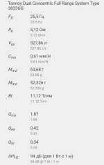
Would you be willing to advise me what portsize to use? Cabinet is +/-145-150LComing a bit late to the 'party' with the usual disclaimers; Vas, Qts' are 'open' from at least ~430-528 L, 0.34 - 0.42 Qts when including these, so using its mean:
sqrt(430*528) = ~476 L mean Vas
sqrt(25.5*27.4) = 26.43 Hz Fs mean
sqrt(5.12*5.5) = 5.31 ohms Re
sqrt(1.87*1.2) = 1.5 Qms
sqrt(0.42*0.537) = 0.475 Qes
0.361 calc'd Qts
0.5 ohm (Rs) = 0.386 Qts'
sqrt(0.34*042) = 0.378 Qts mean Vs 0.361 calc'd!
pioneer's reflex cab ratio = ~476/1.44 = ~331 L net (personal minimum based on Qts').
Below this point, sealed alignment Vb calcs seem more relevant:
265 L
(a) = ~476/265 = ~1.76
Qtc = sqrt(1.76+1)*0.386 = 0.645
Fc = (0.645*26.43)/0.386 = ~44 Hz
BR Fb = 0.645/0.5 = 1.29
26.43/1.29 = 20.5 Hz
=============
145 L
(a) = 476/145 = 3.283
Qtc = sqrt(3.283+1)*0.386 = 0.8
Fc = (0.8*26.43)/0.386 = ~54.8 Hz
BR Fb =0.8/0.5 = 1.6
26.43/1.6 = 16.5 Hz
These vented tunings come closest to sealed re group delay, etc., but simmed with Fs tuning isn't much different and superior if driven with a high output impedance amp.
All that said, the 3833 and 3836 are supposed to be identical spec wise, but based on a 339 cm^2 (Sd), low Fs and ridiculously low Qms, the posted 3833 specs are pure 'floobydust' in that the T/S specs' Cms, Mmd, BL are just small fractions according to HR, so sure would be nice to get some measured specs!
I feel very bad about providing the wrong data in my earlier post. And don't understand what the calculations say.
No big deal: it happens. Afraid I'm stuck at the moment as half the house is torn apart thanks to a water leak, but hopefully will be up to speed again at some point soon.
145 L 3836 specs with minimal added series resistance:
(a) = 430/145 = 2.966
Qtc = sqrt(2.966+1)*0.43 = 0.856
Fc = (0.856*27.4)/0.43 = ~54.55 Hz
BR Fc ratio = 0.856/0.5 = 1.712
27.4/1.712 = 16 Hz Fb
Per HR, this tuning is so far below Fs required to flatten its somewhat high sealed Qtc that it's limited to ~ 4 W/40 Hz/2pi (spaced away from any significant wall/corner loading), though tuning it an octave higher (32 Hz) increases it to 14 W/40 Hz with a calc'd ~3 dB/70 Hz peak referenced to its mid band efficiency, so ideally needs a HP filter to protect it.
Assuming this is OK, then a ~ 4" dia. x 3.5" long vent peaks out at ~ 9 m/s @ 14 W and critically damp the vent to 'taste' to get a great compromise between the two tunings or stuff it to ~ mimic the 16 Hz tuning, though obviously with some power handling loss.
Attachments

Bummer! 🙁 There's been a 'rash' of it both locally and around the USA in general due to the old age of many mains piping, earthquake tremors, forest fires. Fortunately my locale got an overhaul ~ a decade ago plus got a modern water meter, so took advantage of it to replace my meter - house feed to a high pressure hydraulic hose plus appropriate fittings to ensure even withstanding any tree root damage (most common)/normal post hole digging and back when I bought the house the first major upgrade was all new plumbing that still exceeds current codes and 'light years' away from its original 1952 codes.I'm stuck at the moment as half the house is torn apart thanks to a water leak
Considering your country's/cities's much longer history, dare I ask how old/what type building construction/plumbing used?
I'm grateful you want to help.145 L 3836 specs with minimal added series resistance:
(a) = 430/145 = 2.966
Qtc = sqrt(2.966+1)*0.43 = 0.856
Fc = (0.856*27.4)/0.43 = ~54.55 Hz
BR Fc ratio = 0.856/0.5 = 1.712
27.4/1.712 = 16 Hz Fb
Per HR, this tuning is so far below Fs required to flatten its somewhat high sealed Qtc that it's limited to ~ 4 W/40 Hz/2pi (spaced away from any significant wall/corner loading), though tuning it an octave higher (32 Hz) increases it to 14 W/40 Hz with a calc'd ~3 dB/70 Hz peak referenced to its mid band efficiency, so ideally needs a HP filter to protect it.
Assuming this is OK, then a ~ 4" dia. x 3.5" long vent peaks out at ~ 9 m/s @ 14 W and critically damp the vent to 'taste' to get a great compromise between the two tunings or stuff it to ~ mimic the 16 Hz tuning, though obviously with some power handling loss.
I know we are dealing with physics and things are what they are. But did not expect it would be this "complicated".
These units are normally used in way smaller cabinets (System 15 DMT , CPA 15, but also in the Churchill wich is bigger?)
And can be driven with BIG Poweramp's.
I'm also using high power.
My aim is not to have the most extended low end / deepest notes.
My thoughts where to make a bigger cabinet than the DMT or CPA and therefore have a few hz more low end. Sealed /ported or whatever is better.
As I now understand: It's not this simple?
(If I'm correct the DMT's are 100L and has 38hz -3db anechoic. I would be going about half bigger and would be happy with just a few hz lower.)
Beginning to think I'm in way over my head with these drivers.
EDIT: Also want to use the DMT 15 or CPA 15 crossovers with it.
Last edited:
Yeah, not much fun. Wise man, doing your house feed etc. when you got chance. 👍Bummer! 🙁 There's been a 'rash' of it both locally and around the USA in general due to the old age of many mains piping, earthquake tremors, forest fires. Fortunately my locale got an overhaul ~ a decade ago plus got a modern water meter, so took advantage of it to replace my meter - house feed to a high pressure hydraulic hose plus appropriate fittings to ensure even withstanding any tree root damage (most common)/normal post hole digging and back when I bought the house the first major upgrade was all new plumbing that still exceeds current codes and 'light years' away from its original 1952 codes.
Considering your country's/cities's much longer history, dare I ask how old/what type building construction/plumbing used?
It's a brick built semi-deteached at this end, ~1936. Pipe is (was) the original lead. Thanks to the design of these places, you get a central feed between the two houses in the crawl space. The main part of the ground floor is divided into a front & back room, & the pipe does a 90 degree vertical up the corner of that dividing wall to where an old header tank and immersion heater used to be on the 1st floor. Those have long gone, but the pipe still carries the main feed & wombles digonally over between the floors to supply the bathroom, and finally drop down to the kitchen below. Made sense back in '36, not so great 90 years on. Anyway, it decided to let go in the upper corner of the vertical, right under a floor joist. Cue much entertainment, since leaving pipe, ceiling / floor aside, the coving below isn't coving, but the original plaster over a former. And full of asbestos.

I'm grateful you want to help.
I know we are dealing with physics and things are what they are. But did not expect it would be this "complicated".
These units are normally used in way smaller cabinets (System 15 DMT , CPA 15, but also in the Churchill wich is bigger?)
And can be driven with BIG Poweramp's.
I'm also using high power.
My aim is not to have the most extended low end / deepest notes.
My thoughts where to make a bigger cabinet than the DMT or CPA and therefore have a few hz more low end. Sealed /ported or whatever is better.
As I now understand: It's not this simple?
(If I'm correct the DMT's are 100L and has 38hz -3db anechoic. I would be going about half bigger and would be happy with just a few hz lower.)
Beginning to think I'm in way over my head with these drivers.
EDIT: Also want to use the DMT 15 or CPA 15 crossovers with it.
You're welcome!
Nothing complicated about it, quite simple actually: Loudspeaker design tradeoffs
From this we see you 'can't have your cake and eat it too'.
The 'problem' is these loudspeaker forums are primarily for folks wanting to DIY speakers for HIFI/HT/small party apps, so what we default to speaker design wise and when we have conflicting issues we try to present a 'best guess'.
But when folks either give us bad/misleading information and/or don't give us all the desired performance goals and/or which is most important on the front end, we 'default' to the norm and when 'blindsided' with a ~ completely different main performance goal referencing others designs such as you just did plus want to use their XOs, then best to copy their designs and only increase depth to make it bigger since the XO may take the baffle design into account and empirically tune to 'taste'.
Pipe is (was) the original lead.
Lead??!! Asbestos! Ugh! Had to remove a 'ton' of insulation, exterior siding made of it, though thankfully I got it done right before the Feds made it illegal to do such things/disposal by all but approved folks/methods at huge cost.
Regardless, hope the weather doesn't make it too horrible/costly to get done and of course hope you've got decent hazmat protection as I've known way too many folks that died relatively young from this stuff, including some (extended) family.
You're welcome!
Nothing complicated about it, quite simple actually: Loudspeaker design tradeoffs
From this we see you 'can't have your cake and eat it too'.
The 'problem' is these loudspeaker forums are primarily for folks wanting to DIY speakers for HIFI/HT/small party apps, so what we default to speaker design wise and when we have conflicting issues we try to present a 'best guess'.
But when folks either give us bad/misleading information and/or don't give us all the desired performance goals and/or which is most important on the front end, we 'default' to the norm and when 'blindsided' with a ~ completely different main performance goal referencing others designs such as you just did plus want to use their XOs, then best to copy their designs and only increase depth to make it bigger since the XO may take the baffle design into account and empirically tune to 'taste'.
I only wanted to use Hondasnl's design/look. I very much love this look. Increadible woodwork.
The frontpanels are allmost the same in size as the system 15 dmt ii. (so i would only have to make little adjustments to hondasnl's design)
Reading all the usefull information i will stick to the original internal volume of the system 15 DMT and use the 110mm OD x250mm port tubes mentioned in the service manual. Better be safe.
Thanks again.
- Home
- Loudspeakers
- Multi-Way
- Tannoy 3836