Hi Mike,
Thanks for pitchin in!
Tuning in on your disassembling guidelines I know you're probably right there but I have examined the wiring and it looks though that there's a problem that the wires are too short but I could be wrong and all that is needed to cut all the tire-wraps.
I've downloaded and read Jim Hagerman's of Hagerman Technology article called 'Calculating Optimum Snubbers' (paper can still be found online) on the subject of snubbers and although the calculus is abracadabra for me it seems to be very usefull to perform such an operation. Need four of those snubberboards for one pair of SA/1's of course.
Some graphs from the Jim Hagerman paper on implementing snubbers on PSU's:


So Fig. 12 is Fig. 10 and 11 combined.
Did some querying on DIYAudio with snubberboard AND user rhthatcher but I couldn't find anything though but that's probably me.
Did measure all the emitterresistors on top of the heatsinks and got values coldstarted ranging from 120 to 135mV.
So it seems okay.
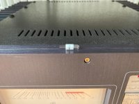
Another thing I noticed as on my earlier Threshold amps there's a lot of fluxresidue everywhere:

Is that a problem because other manufacturers tend to remove that as I recall.
Well it still works after almost 40 years so they seem to be very rock solid designs rarely found at repair service-stations as I vented before on this forum.
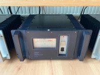
Some users qualify these SA/1 amps as the pinnacle design of NP maybe because of the right amount/balance/stasis ;-) of the parts combined together as the sum of the parts. I think the pretty meters do have something todo with it because the frontendboards are basically all the same (I know that there are different incarnations as you stated even a 2020 version from NP) and only the outputdevices and PSU grows with the more powerfull versions. But I'm easy to accept another opinion on this matter because of lack of knowledge.
Thanks for pitchin in!
Tuning in on your disassembling guidelines I know you're probably right there but I have examined the wiring and it looks though that there's a problem that the wires are too short but I could be wrong and all that is needed to cut all the tire-wraps.
I've downloaded and read Jim Hagerman's of Hagerman Technology article called 'Calculating Optimum Snubbers' (paper can still be found online) on the subject of snubbers and although the calculus is abracadabra for me it seems to be very usefull to perform such an operation. Need four of those snubberboards for one pair of SA/1's of course.
Some graphs from the Jim Hagerman paper on implementing snubbers on PSU's:
So Fig. 12 is Fig. 10 and 11 combined.
Did some querying on DIYAudio with snubberboard AND user rhthatcher but I couldn't find anything though but that's probably me.
Did measure all the emitterresistors on top of the heatsinks and got values coldstarted ranging from 120 to 135mV.
So it seems okay.
Another thing I noticed as on my earlier Threshold amps there's a lot of fluxresidue everywhere:
Is that a problem because other manufacturers tend to remove that as I recall.
Well it still works after almost 40 years so they seem to be very rock solid designs rarely found at repair service-stations as I vented before on this forum.
Some users qualify these SA/1 amps as the pinnacle design of NP maybe because of the right amount/balance/stasis ;-) of the parts combined together as the sum of the parts. I think the pretty meters do have something todo with it because the frontendboards are basically all the same (I know that there are different incarnations as you stated even a 2020 version from NP) and only the outputdevices and PSU grows with the more powerfull versions. But I'm easy to accept another opinion on this matter because of lack of knowledge.
do not worry about flux
same as recent fascination about solder pads, Greedy Boyz expecting to see solder in same way on both sides of solder pads (somehow solder needs to behave as water, regarding capillary effect), there is entire People's Movement for Cleaning Da Flux!
if stage is not exactly FM Tuner input section, I'm not bothered even to think about flux, when using proper solder
It's great to get all enthusiastic for a common cause although it seldom lasts very long...there is entire People's Movement for Cleaning Da Flux!
Maybe life is too complex to strive for unipolar solutions.
I'm mostly lost experiencing the free floating anxiety creeping up inside my psyche.
Attachments
Here is RhThatcher. He sells those little snubber boards in a kit. I believe he might sell the snubbers seperately.
You use a tool called the Quasimodo with an oscilloscope to measure ringing. It looks complicated but it is much simpler than it looks. You will need to look for the latest Gerber file, upload and have it printed at a place like JLCPCB.com. There should also be a Bill of materials in the thread. Probably close to the where the Quasimodo file is posted.
I used the Cheapomodo which is a little simpler and supposed to be cheaper. However, I don't feel that it was much cheaper. It is a little simpler to use though.
The board can be powered by an old wall wart type power supply, a 9v battery, or whatever really as long as it is within the voltage spec. I believe it can run off of anything from 5-15v. The actual spec is in the literature.
It is a bit of work. However, my stasis amp really improved after doing the snubber stuff. I figured since you may be taking the heatsinks off to measure things, then it would be worth it.
Regarding the flux, mine had flux throughout it. When I was doing all the work to it, I cleaned it up as I went along. But it has been there for 40 years like you said so really up to you.

Thanks Mike,
I will look into it and I first have to find some courage to endeavor the disassembly procedure but when it is out of the way I could perform all the duties I'm panning maybe even swapping out the 35 year old Mallory's...
I will look into it and I first have to find some courage to endeavor the disassembly procedure but when it is out of the way I could perform all the duties I'm panning maybe even swapping out the 35 year old Mallory's...
I measured a railvoltage of 56 Volts. I know it's specified at 62 Volts.
I've only 4x29.000uF per channel can raise it to 4x100.000uF but that could be stressful for the rectifiers and On/Off Airpax circuitbreaker.
I've only 4x29.000uF per channel can raise it to 4x100.000uF but that could be stressful for the rectifiers and On/Off Airpax circuitbreaker.
You would likely need some sort of soft start. I can't remember if my S/500 came with a thermistor on the mains or not. The power supplies are kind of primative on these old dogs.
There is a soft as a pillow.
https://www.diyaudio.com/community/...-pillow-sfp-ssr-soft-start-circuit-gb.350441/
I installed the soft start from the DIYaudio store onto the back of my faceplate of mine. It works well Since you have a double faceplate, you can do a through hole on the inner faceplate (the one with the handles).
So I am recommending the soft as a pillow even though I have not used it because the current version uses Thermistors instead of resistors. With the resistor based ones, if the relay fails to swich the mains off of a resistor based one, the resistors get really hot and burn up since the resistance does not change enough with temperature. Thermistor's resistance will lower as they heat up and they won't burn up.
Another thing you could try is maybe the thermistors accross the mains setup. Like you would see on a Firstwatt clone style (you can find this in the build guides. Although, I think CL-60's may be enough, you would want to check. They are rated at 5 amps I believe.
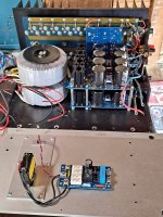
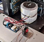
If I am correct, I believe you have a center-tapped single secondary. So maybe a 88v rail split down the center. You can share a few pics of the inside if you like. 🙂
There is a soft as a pillow.
https://www.diyaudio.com/community/...-pillow-sfp-ssr-soft-start-circuit-gb.350441/
I installed the soft start from the DIYaudio store onto the back of my faceplate of mine. It works well Since you have a double faceplate, you can do a through hole on the inner faceplate (the one with the handles).
So I am recommending the soft as a pillow even though I have not used it because the current version uses Thermistors instead of resistors. With the resistor based ones, if the relay fails to swich the mains off of a resistor based one, the resistors get really hot and burn up since the resistance does not change enough with temperature. Thermistor's resistance will lower as they heat up and they won't burn up.
Another thing you could try is maybe the thermistors accross the mains setup. Like you would see on a Firstwatt clone style (you can find this in the build guides. Although, I think CL-60's may be enough, you would want to check. They are rated at 5 amps I believe.
If I am correct, I believe you have a center-tapped single secondary. So maybe a 88v rail split down the center. You can share a few pics of the inside if you like. 🙂
Attachments
How about this thermistor:
https://www.mouser.com/ProductDetail/Ametherm/MS35-10018?qs=PVyXUKBeRH3sUEikFWbR5w==
https://www.mouser.com/ProductDetail/Ametherm/MS35-10018?qs=PVyXUKBeRH3sUEikFWbR5w==
That seems like it may work. Both are 10 ohms.
MS35-10018
Resistance @ 100% Max Current: 0.05
Resistance @ 50% Max Current: 0.15
Body Temperature at 100% Max Current: 215.00 °
MS35-10018
Resistance @ 100% Max Current: 0.05
Resistance @ 50% Max Current: 0.15
Body Temperature at 100% Max Current: 215.00 °
Like this:I installed two DIYaudio power supply boards which are CRC. I have 8x22000uf per channel. Mine runs at +-39vdc rails. I believe yours is +-62vdc rails.
Kemet ALS30 are some good caps but can be pricey.
https://www.ebay.com/itm/174334494816
Yeah, sort of. Here are the boards:
https://diyaudiostore.com/collections/frontpage/products/universal-psu
If you are thinking of doing this, check to make sure high-voltage caps will fit. Mine has lower voltage rails which makes it a little easier to pull this off (smaller caps). Also, your transformer is a different setup. I think going with some nice large caps and some snubbers will set you up nicely.
Yes Mike, I think that too and I will try the 10 Ohm thermistor also.If you are thinking of doing this, check to make sure high-voltage caps will fit. Mine has lower voltage rails which makes it a little easier to pull this off (smaller caps). Also, your transformer is a different setup. I think going with some nice large caps and some snubbers will set you up nicely.
I'm in doubt about the parallel filmcaps to use that ZenMod advised to be at least over 4.7uF.
Something like this with a 40uF rating?there is a sorta tedious way of deciding/investigating is it clever to replace main caps, even if there is no hum
simply connecting additional caps across original ones, then listening and (God Forbid!) measuring - is there any positive change
of course, that must be done in a way that connecting wires are shortest possible, fattest possible etc.
and - of course, one must have on disposal adequate caps for test
I mean - there are cases where caps are tired.....not so tired to hum becomes present, but tired enough to sound start deteriorating
I know that I didn't help now at all, but that's the fact, and I had experiences as that in the past (say Hafler DH200 and 220 - huge difference in sound, even if tehre was no hum in speakers; Quad 405 - same case..... and interesting - main caps aren't so important for hum, as small caps on pcb are ... )
remember that amp (active part of it) can be seen as black box which is doing nothing else than governing PSU energy to speaker, in convenient manner
https://www.soundimports.eu/en/dayton-audio-dmpc-40.html
Whatever Zen Mod says is gold! 🙂Yes Mike, I think that too and I will try the 10 Ohm thermistor also.
I'm in doubt about the parallel filmcaps to use that ZenMod advised to be at least over 4.7uF.
Haha, that's true.Whatever Zen Mod says is gold! 🙂
Well I have some very expensive V-Cap CuTF Teflon caps but only with a .22uF rating and according to ZenMod that won't do that much.
A friend of mine is fairly experienced with electronics. He used to have a company designing Hi-Fi gadgets similar to the ones we play with. He suggested solen for power supply. Pass labs has used I believe clarity cap PX series in their preamps.
10uf is a common value. If that is something that will be within the range of what ZenMod suggests, that's probably what I would try. 10uf is used in a lot of PassDIY stuff. BA3 preamp/amp in particular
Rereading Zen mods post about adding caps to check old capacitors, he may be talking about large power supply type caps like say 10, 000uf and above.
I thought he was pointing to this:Rereading Zen mods post about adding caps to check old capacitors, he may be talking about large power supply type caps like say 10, 000uf and above.
https://www.diyaudio.com/community/threads/threshold-sa-1-hiss.380904/post-6906037
play with something more substantial - from 4u7 upwards
100n is in realm of placebo
Something like this with a 40uF rating?
https://www.soundimports.eu/en/dayton-audio-dmpc-40.html
for that test - adding substantial capacitance, at least 10mF across each existing Bigun
adding solid block ones across main reservoir caps is matter of noise/speed/better sleep
- Home
- Amplifiers
- Pass Labs
- Proper biasing Threshold SA/1s