I have finally managed to source Z11 0.35mm laminates and is about to wind an output transformer for a low power guitar amp project. I wound a few before, using repurposed power transformer laminates (0.55mm), with surprisingly good results.
To get the inductance per turn on previous cores, i would 1000 turns and measured. This is a waste of copper though, so I wonder if there is a generic rule to estimate inductance per turn for Z11 0.35mm EI laminate given the core area?
Thanks in advance,
Mike

To get the inductance per turn on previous cores, i would 1000 turns and measured. This is a waste of copper though, so I wonder if there is a generic rule to estimate inductance per turn for Z11 0.35mm EI laminate given the core area?
Thanks in advance,
Mike
You didn’t save the wire from the last test winding? I never throw away magnet wire unless it is totally trashed. I might never put high voltage on it again, but it’s always useable for something. Like this.

I did save them (I have a massive squirrel complex), but the new cores are larger so it wont fit.
Got enough for 100 turns? 50? Bigger core needs less turns anyway.
”Massive squirrel complex” -LOL. You should have seen the pile of acorns I found inside one of my big horn loaded subs a month or so ago.
”Massive squirrel complex” -LOL. You should have seen the pile of acorns I found inside one of my big horn loaded subs a month or so ago.
Audio transformers are undistinguishable from power trafos. Apply the same math using the lowest frequency you want the trafo be able to pass and the desired induction. When unknown data, I use 8000 gauss or 0.8T (the same). Use the AC RMS voltage at the primary. And in case of DC premagnetization, don't worry. You can test and adjust gap it in situ.
The issue with this bobbin with separate space for primary and secondary will be the increased leackage inductance. IMO I would wound 1/4 pri in each semi-bobbin (let me create a neologism). Thus, 1/2 secondary in each sector after isolation, and thus, end with 1/4 pri in each them.
This wise you mantain toguether low leackage inductance and low capacitance.
This trafo reused core from verical deflection and perform ultralinear using ECL85 pentode without issues.
Attachments
If you know the geometry and material of the core you should be able to calculate the inductance per turn squared. The inductance is proportional to the square of the turn number.
To correct for measurement error you can use several numbers of turns to have as many inductance values. Then, use a scientific calculator to find the linear regression line. If you plot the inductance against the square of turns, the gradient will be what you want.
To correct for measurement error you can use several numbers of turns to have as many inductance values. Then, use a scientific calculator to find the linear regression line. If you plot the inductance against the square of turns, the gradient will be what you want.
Not worth trying to calculate. Inductance will depend on many parameters. Some of these parameters are easy to determine (cross-section, magnetic path length), but others not so (mu, stacking factor, effective gap). Furthermore, inductance depends much on frequency and AC voltage amplitude. So, wind a test winding and measure it under your specific conditions.
You don't need to use big wire just to test inductance either. You can hack the primary wire out of an old wall wart or something, and turn away.

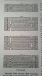
You can linearise the magnetic response of the core by using an airgap in the magnetic circuit. However, this will require more current for the same magnetic intensity with the result the constant of inductance becomes smaller. Hence more turns are needed for the same inductsnce.
There formulae and methods to calculate the experimental error. I used them in my batchelor degree.
There formulae and methods to calculate the experimental error. I used them in my batchelor degree.
0.35mm is really thick for audio applications. Anyway, you can use whatever number of turns you find convenient for testing. 1 turn would be unpractical because of the low voltages/high-currents involved, but I regularly use 10 turns, as it makes calculations easy and straightforward.
The level of excitation depends on your application, and your test should match it for a good accuracy: an incorrect level could cause a near 1:10 error ratio
The level of excitation depends on your application, and your test should match it for a good accuracy: an incorrect level could cause a near 1:10 error ratio
L =( 1.257*mu*N^2*Ae)*10^-8/Lmso I wonder if there is a generic rule to estimate inductance per turn for Z11 0.35mm EI laminate given the core area?
where,
N^2 is the squared number of turns, mu is the effective permeability (I suggest using the small signal permeability for SE application which usually spans from 200 to 450 otherwise for PP use 1500 for small signal to 5000 for max value, with minimal gap), Ae is the effective core cross-section (measure the inner core surface and multiply by the stacking factor of 0.95) in square cm, Lm is the average magnetic path length in cm which you can compute by taking the nominal size of the lamination (it's the width of the centre leg of the E) and multiply by 6. The factor 10^-8 will give you the result in Henry.
Last edited:
@45, thanks! I tried this before and for could for some reason never make sense of the figures, maybe because i misunderstood some of the factors or mixed up the units. I wound 500 turns and measured inductance under ~50% load and measured 7H. Plugging that in gives mu = 4690 which would be close to expected results. Does this look right to you:

I have a few guitar amp transformers and it looks to me like 0.35mm or 0.55mm is typical. What is typical for HiFi?0.35mm is really thick for audio applications.
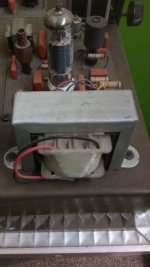
This is a PP amp (2 x EF80), so no need for gap. I cut off the center divider and will wind 3:2 interleave this time as the increased permeability allows much less turns. I used 4:3 interleave on the last transformer for that reason, pictured below. Primary impedance was 20K, but the next will be 25K to get a better fitted load line given 250V that i have available.Audio transformers are undistinguishable from power trafos. Apply the same math using the lowest frequency you want the trafo be able to pass and the desired induction. When unknown data, I use 8000 gauss or 0.8T (the same). Use the AC RMS voltage at the primary. And in case of DC premagnetization, don't worry. You can test and adjust gap it in situ.
The issue with this bobbin with separate space for primary and secondary will be the increased leackage inductance. IMO I would wound 1/4 pri in each semi-bobbin (let me create a neologism). Thus, 1/2 secondary in each sector after isolation, and thus, end with 1/4 pri in each them.
This wise you mantain toguether low leackage inductance and low capacitance.
This trafo reused core from verical deflection and perform ultralinear using ECL85 pentode without issues.
This is all new to me and i don't understand what you mean. Would you mind to elaborate and educate me? 🙂SwedishWings uses EI core, therefore, he can create small quasi-distributed air gap to linearise permeability/inductance using different assembly methods.
1:1 - 0.013mm, 4:4 - 0.025mm, 8:8 - 0.051mm, 16:16 - 0.102mm.
Hehe, i think they are the cutest animal on the planet. Sweden, with its long dark winters with limited food have over thousands of years caused genetic cleansing of people who was not able to store food for the winter. I consider that a valid excuse for my behavior.Got enough for 100 turns? 50? Bigger core needs less turns anyway.
”Massive squirrel complex” -LOL. You should have seen the pile of acorns I found inside one of my big horn loaded subs a month or so ago.
Last edited:
I measured lamination thickness in over 30 different audio transformers from vintage tube amplifiers. 0.35 mm was typical thickness. Anything thinner than that is exotic stuff.I have a few guitar amp transformers and it looks to me like 0.35mm or 0.55mm is typical. What is typical for HiFi?
- Home
- Amplifiers
- Tubes / Valves
- Estimating inductance per turn