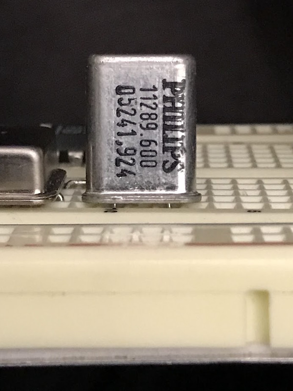
Here is my long-time Philips friend that needs a nice, clean oscillator circuit. Please help my friend!
The popular, but closed Well Tempered thread is here:
https://www.diyaudio.com/community/...phase-noise-jitter-crystal-oscillator.261651/
I downloaded all of andrea_mori's PDF files but am a bit perplexed as to which particular circuit to use for my Philips, if any.
Maybe another circuit exists that's better suited to the old Philips osc.
Also, what ever happened to Laptech group buys? Can one still purchase them? Or osc's of equal quality from another manuf.?
Maybe the "cut" of the crystal isn't as important at the clcok/osc circuit it is encapsulated by? Yes?
Your pic shows a crystal, right? So, what is it you want? Do you want a new oscillator circuit that can use the existing crystal? Do you want a new crystal to work with existing oscillator circuit? Do you want to replace all that stuff with a good clock module?
If you want to use any of the existing clock circuitry and crystal then you probably should keep it all. That's because oscillator circuits and particular crystal types have to be designed to work together.
If you want to use any of the existing clock circuitry and crystal then you probably should keep it all. That's because oscillator circuits and particular crystal types have to be designed to work together.
A simple, diy clock (oscillator) circuit is what I'm looking for. I've veroboard built several in the past, some based on 2-pin crystals, other based on 4-pin osc's. That 11.289 placement in the orig. CD player is the Xo/Xi pins of the SAA7220A digital filter. Not ideal.If you want to use any of the existing clock circuitry and crystal then you probably should keep it all. That's because oscillator circuits and particular crystal types have to be designed to work together.
But, I don't know what the cut of the orig. Philips crystals are. I doubt they were $$$ precision cuts like Laptech. Yes, the type of cut can affect the crystal impedance, and they might help in choosing the correct osc/clock topology. E.g., LC tanks, Clapp, Colpitts, Pierce.
https://www.electronics-tutorials.ws/oscillator/crystal.html
What voltage clock signal does the existing circuit output?
Also, that nominally 11.2896MHz clock is only good for 44.1kHz family sample rates. CD audio and possibly multiples thereof. Is that all you want?
Also, that nominally 11.2896MHz clock is only good for 44.1kHz family sample rates. CD audio and possibly multiples thereof. Is that all you want?
I think you can just use an HC04 in a configuration like this : https://cn.bing.com/images/search?view=detailV2&ccid=2HSlsi7Q&id=33A665E6916DE2DBCF7295190CE431DEB39178B3&thid=OIP.2HSlsi7Qe5t22Ir6irEzaQHaFt&mediaurl=https://www.electronics-lab.com/wp-content/uploads/2016/07/figure2-600x463.png&cdnurl=https://ts1.cn.mm.bing.net/th/id/R-C.d874a5b22ed07b9b76d88afa8ab13369?rik=s3iRs94x5AwZlQ&pid=ImgRaw&r=0&sres=1&sresct=1&srh=799&srw=1036&exph=463&expw=600&q=single+inverter+xtal+oscillator&simid=608018239706433081&FORM=IRPRST&ck=E6D5F9C9AAD55800DF2AD2A628E8D2F0&selectedIndex=8
(I'd not use HC14 as that has hysteresis)
(I'd not use HC14 as that has hysteresis)
Do you have a schematic for the original Philips circuit? Maybe a service manual for the device it came out of?
Seems likely the original osc was inside the SAA7220 digital filter chip. This acts as clock master in Philips CD players of that generation. Clipped from SAA7220 DS :

The HC04 looks interesting.
I've Veroboarded some high-performance clocks, and related projects, in years past. The "multi-story" device is the photos below is, I believe, a Kwack Clock, a re-clocker and a divide-by-2 (all-in-one) contraption.
Been out of practice for many years ... forgotten what I did here ... one of the Vero's is a Flea Clock (???). The "Henk" Vero's may be re-clockers (?????)
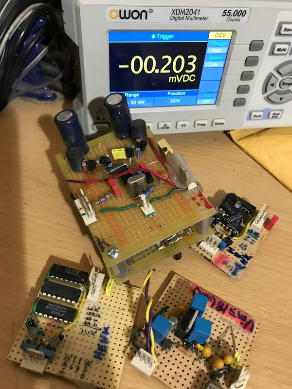
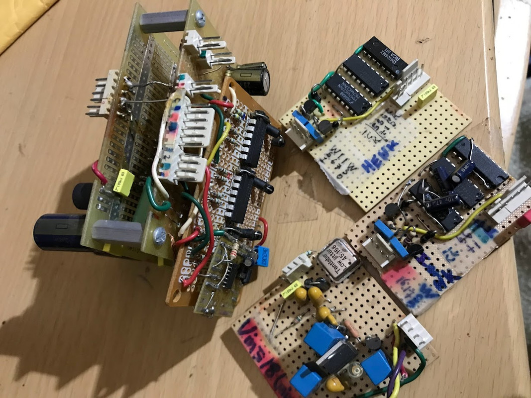
I see a Tentlabs low jitter clock on one of your boards. That contains all electronics besides the crystal. You just divide its output by 4 and ready to use.

Yes.I see a Tentlabs low jitter clock on one of your boards. That contains all electronics besides the crystal. You just divide its output by 4 and ready to use.
Guido Tent discusses this here:
https://www.tentlabs.com/Components/XO/assets/Divide by 2 V2.pdf
Including a divide by circuit.
I also have a couple of Guido's dedicated 11.2896 Mhz osc's which are in are actively in use.
The strange thing is, in the original application (TDA154(a), the 11.2896 Mhz is not what's used by that DAC. It must be divided in half:
f_BCK clock input pin 2: 6.4 MHz (max):
http://www.lampizator.eu/lampizator/LINKS AND DOWNLOADS/DATAMINING/tda 1541A.pdf
Even stranger: The datasheet for the TDA1541 (not "a"):
Input frequency (max):
at clock input (pin 4) fSCK − − 12 MHz
at clock input (pin 2) fBCK − − 6 MHz
at data inputs (pin 3 and pin 4) fDAT − − 6 MHz
at word select input (pin 1) fWS − − 200 kHz
https://pdf.datasheetcatalog.com/datasheet/philips/TDA1541.pdf
I'm not sure how unclean (jittery) the clock signal becomes after going thru multiple divisions (even if they are integer divisions)?????
And that same doubt about jitter can apply to all the glue logic used in re-clockers (how useful is re-clocking ... ultimately???).
About the weird osc. freq arrangement of the classic SAA7210 (decoder) -- >>> SAA7220 ->>> TDA1541A trifecta.
XSYS (SAA7220) sends 11.2896 Mh/2 to both the clock inputs of SAA7210 (decoder) and TDA1541A
https://pdf.dzsc.com/SAA/SAA7220.pdf
https://pdf1.alldatasheet.com/datasheet-pdf/view/19037/PHILIPS/SAA7210.html
I am assuming that the SAA7210 also does 11.2896 Mhz / 2 (internally) because many NOS modders just jumper over 7220 to the 1541 directly. Or maybe the 7220 is kept in the NOR arrangement, but only as the clock generator/divider ??????
fWS = 176.4 kHz (4x OS)
fBCK = fWS x 16 x 2 = 5.6448 MHz
The master clock fSCK = 11.2896 MHz is used by the TDA1541, but not used by the TDA1541A. In both case it is used by the decoder and the digital filter. I don't see any contradiction. It seems the TDA1541 contains a reclocker, but the TDA1541A does not. I am not quite sure.
The contradiction is in the DS of the SAA7220 (pg 19). The SAA7220 is sending 5.6448 MHz (XSYS) to both the SAA7210 and TDA1541.I don't see any contradiction. It seems the TDA1541 contains a reclocker, but the TDA1541A does not. I am not quite sure.
About reclocker .... I meant aftermarket and DIY re-clockers (see my photos, i.e, HENK). Because they increase signal trace path and add complexity.
philipsmarantz, it might help if you would just state what your end goals are. We can cut to the chase and better advise on how to get to where you want to be. If is that you simply want the crystal to oscillate in isolation just to have made it do so yourself, fine. OTOH maybe you really want something more than that in the end?
You asked the same before and I replied here:philipsmarantz, it might help if you would just state what your end goals are. We can cut to the chase and better advise on how to get to where you want to be. If is that you simply want the crystal to oscillate in isolation just to have made it do so yourself, fine. OTOH maybe you really want something more than that in the end?
https://www.diyaudio.com/community/threads/philips-11-289mhz-osc-needs-clock.395358/post-7260812
Interesting that you use the expression "cut to the chase" because that is part my investigation about the Philips ... how was it cut? (As noted earlier).
It's possible that one doesn't need to about the cut or other manuf specs about the crystal as long as one can bench-tweak the tank circuit by hand .
Say by using pots or variable capacitors --- yes?
It would be cool to have that old Philips perform very well and stably ... well beyond the OEM cd player circuit .... but keeping the parts count minimal. No more Kwack Clocks!...just state what your end goals are...
EDIT:
On the other hand, I always wanted to build the Jocko Clocko, but never got around to it:
https://www.diyaudio.com/community/threads/low-noise-oscillator.6194/
Pretty complex.... but it might be fun.
Last edited:
I was an acquaintance of Jocko closer to the end of his life. We talked on the phone about clocks several times. Have a few of his selected NDK SDA clocks too. Also, I am in continuing contact with Adrea Mori, designer of the more or less SOA crystal clocks you referred to at one point. Andrea visited my home over the summer when he was in CA for holiday. Brought his audio travel companions with him. Have his latest DSD-only prototype dac here for listening tests. He said my oversampling AK4499 dac was like no other oversampling dac he ever heard before. No digital glare at all, easy to tell a Steinway piano from other manufacturers, etc.
I can tell you how to make one heck of great clock system from off the shelf components if you know how to lay out a PCB. IMHO your old Philips crystal is in reality more like quaint history. So again, what do you want? Do you want a clock much better than any other part of your dac? If so, I could tell you how to make one. Or, would you like to play around with CMOS inverters, if that sounds fun? Really depends on what you want to do for a hobby.
Or we could just try to respond to your questions as though you know how to ask the right ones for whatever it is you want to do. I keep trying to figure out what it is you really want is all.
Not sure ... these diy projects seem to come into their own ... especially as these posts and ideas develop.So again, what do you want?
Getting a really good crystal seems to have become a personal obession at the time. Good ones at 11.2896 are almost impossible to find these days. Unfortunately, I was out of the loop when the Laptech GB was in full force .
Tell away ... But ... although I do use SPlan and JLPCB for some projects, I very rarely create audio projects on anything but Veroboard. I like components to be as close as possible, and traces nice and thick. Can't do that on those green things.I can tell you how to make one heck of great clock system from off the shelf components if you know how to lay out a PCB.
But, I don't know what the cut of the orig. Philips crystals are.
Educated guess: must be AT, fundamental mode.
Considering their size, I would expect the static capacitance to be about 4.5 pF. The motional capacitance for an AT-cut, fundamental mode crystal is typically 200 to 300 times smaller, so about 20 fF.
I used to have an old Philips quartz crystal databook, I'm not sure if I still have. I'll have a look later.
Last edited:
Here is some info on quarz vibration modes:
https://www.electronics-notes.com/a...l-xtal/crystal-resonator-cuts-at-bt-sc-ct.php
I doubt you will encounter an SC-cut 11.2896 MHz crystal, it is so special.
Another interesting info:
https://blog.bliley.com/maintain-ultra-low-phase-noise-in-crystal-oscillator-circuits
https://www.homemade-circuits.com/understanding-crystal-oscillator-circuits/
If I remember correctly, a transistor based oscillator with sinusoidal output always outperforms a TTL/CMOS oscillator. You can convert sine to square with a common emitter transistor stage.
Some vague memory tells that a serial resonance crystal and a Butler oscillator has low phase noise - need to check.
Not sure if that is needed (tho' it would be nice to have and experiment with).I doubt you will encounter an SC-cut 11.2896 MHz crystal, it is so special.
Per the classic investigation by Jocko, decades ago (as as noted on the OP of AM's Well-Tempered thread):
I think some cheap 11.289 Citizen crystals are still avail. from DigiKey.The true guru in this matter, that you probably know as Jocko Homo, has demonstrated that one could build a low phase noise oscillator taking a crystal from the shelf with a simple pico gate. He did reach -122 dBC@10Hz from the carrier for a 11.2896 MHz oscillator, that's an impressive result.
But he did a strong selection of the crystal using a phase noise measurement system that costs 30,000 USD or more.
Moreover the crystals he had used, around 0.5 USD each from Mouser or Digi-Key, are no longer manufactured, and the supplier don't have anymore in stock. They were the cylinder crystal CSA309 from Citizen.
He also tested the HC49 type, but seems it's not perform like the above type.
You have to consider also that after the selection, only a few crystals can reach similar performance when placed in the oscillator, usually not more than 5%.
The other crystals were throw out, so the cost increases.
https://www.digikey.com/en/products/detail/citizen-finedevice-co-ltd/HC-49-U-S11289600ABJB/5970768
But the above may be quite different from the Citizen Jocko selected. Thad said: They are still cheap, in stock (by a reputable distributor) , made by Citizen, the correct freq in fundamental mode, and one can pamper them quite a bit using a good, low-noise osc.
============
On a side note, my osc. projects can be THIS simple:
One usually uses 74HCU04 rather than 74HC04 (single inverters rather than groups of three in a row).I think you can just use an HC04 in a configuration like this : https://cn.bing.com/images/search?view=detailV2&ccid=2HSlsi7Q&id=33A665E6916DE2DBCF7295190CE431DEB39178B3&thid=OIP.2HSlsi7Qe5t22Ir6irEzaQHaFt&mediaurl=https://www.electronics-lab.com/wp-content/uploads/2016/07/figure2-600x463.png&cdnurl=https://ts1.cn.mm.bing.net/th/id/R-C.d874a5b22ed07b9b76d88afa8ab13369?rik=s3iRs94x5AwZlQ&pid=ImgRaw&r=0&sres=1&sresct=1&srh=799&srw=1036&exph=463&expw=600&q=single+inverter+xtal+oscillator&simid=608018239706433081&FORM=IRPRST&ck=E6D5F9C9AAD55800DF2AD2A628E8D2F0&selectedIndex=8
(I'd not use HC14 as that has hysteresis)
- Home
- Source & Line
- Digital Line Level
- Philips 11.289mhz osc needs clock