Dear George,Hi Ian
An easy and risk free way is to bypass the input buffer and drive the main board directly, differential or single ended. It is a bit of low Rin (around 7kOhm differential, 3.5kOhm single ended)
Cannon fodder, b1 buffer is
https://www.passdiy.com/project/preamplifiers/b1-buffer-preamp
George
I thought about something a bit simpler because I'm not a professional.
I will stay with it that way.
It's nice, surely for the price.
Hi zoom.@gpapag hi George, from the pics you posted above, are you using SE to Balanced transformers to drive the amp directly without the I/O board op amp buffer?
So far I have listened to this amp with it’s own buffer (SE), without the buffer (SE) and with an input transformer withought it’s own buffer.
The pre amp I am currently using is a passive, high output impedance (100kOhm potentiometer), thus an improper case for driving an input transformer which in turn is connected to a low Rin amplifier. Preamplifier loses steam but aside of this (or because of this), transformer imposes it’s character on the sound. Rich in harmonics, a tad attenuated and velvet highs. With a discrete components buffer, combo will be technically correct. Only then acoustic tests will be of some value to anyone, me included.
For now the amplifier with it’s own buffer is good for driving the Visaton B200 as FR together with a 12Inch passively low passed in an OB configuration. Long term non-fatiguing, with grip and well balanced.
For the active crossover version, I will use two amplifiers with their own buffers, one amp for the OB woofer and one for the subs. For the Visatons, among 5-6 amplifiers, this unit remains a strong candidate but I will play with it’s front end for a while.
George
Last edited:

Hi IlanI will stay with it that way.
Live with it for some time. It's a good companion. Easy to integrate in your system, silent, reliable and balanced.
George
Last edited:
I did have time to test it on Saturday, it sounded great!
Now to figure out an enclosure. I have a closed AL box of the right size for the amp itself, but it has no ventilation and I don't know that I want to try to hand mill it.
I did not see a reference to the LED in the datasheet, did I miss it? Besides the obvious one next to the switch, I see what appears to be standby and power on the input board, but I am not versed enough to figure out other ones. For instance @Fsatsil mentioned clipping, and there was a red LED on the amp unit itself lit, which may be another power one, etc.
The clipping indicator leds are on the input bufffer board, there are four tiny surface mount leds that can easily be mistaken for a resistor if you don’t look closely.

Thanks! And I see the glow from the red LED on the main board (reflection on the heatsink without the temperature probe), so I assume that LED is not a fault indicator.
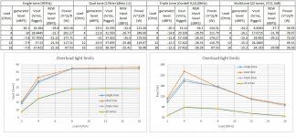
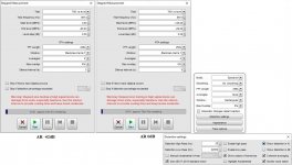
I have investigated the operation of the two clipping (or ‘overload’) red LEDs (the two innermost leds on the input buffer board).
Shown is the output voltage and output power level at which they start to glow (actually 0.1dB before LED turn on dim, just visible under dark ambient background).
I tested operation under four different loads and I used four different test signals.
George
Shown is the output voltage and output power level at which they start to glow (actually 0.1dB before LED turn on dim, just visible under dark ambient background).
I tested operation under four different loads and I used four different test signals.
George
Attachments
I tried using my input trans in the SE:BAL configuration, bypassing the op amp stage on the IO board. It doesn't sound appealing due to the low Rin, I guess. I switched to discrete FET buffer, without the Op amp stage on the IO board. The amp is sounding so impressive now. Opens up the soundstage. Less forward than the op amp stage, but there is much better separation and there are some micro details in the music that I didn't notice before. And without the gain of the IO board, the sensitivity of the input is now very acceptable for use with my preamp.Hi Ian
An easy and risk free way is to bypass the input buffer and drive the main board directly, differential or single ended. It is a bit of low Rin (around 7kOhm differential, 3.5kOhm single ended)
Cannon fodder, b1 buffer is
https://www.passdiy.com/project/preamplifiers/b1-buffer-preamp
George
The FETs are closely matched and it is DC coupled to the amp inputs.
Attachments
Last edited:
I switched to discrete FET buffer, without the Op amp stage on the IO board. The amp is sounding so impressive now.

What is the schematic? I see four semiconductors per channel
George
it seems to me a version of this one.What is the schematic? I see four semiconductors per channel
https://www.aliexpress.us/item/2255800641349314.html?gatewayAdapt=glo2usa4itemAdapt&_randl_shipto=US
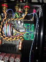
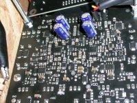
Folks, yes it is the one posted above, but i matched the FETs and installed trimmers to null out the dc offsets. The trimmer pots are under the board, you cannot see it in the picture. I removed the 100pf caps at the input upon some member's recommendation somewhere. Ignore the 22uf caps across the 15k resistors.

George, I used 250 Ohm multi-turn as suggested by another member here in diyaudio. It works beautifully.
I am unable to hunt down an old thread which this buffer was discussed quite some years back, iirc John Curl looked at it and gave it a nod.
Thank you zoom.
Now the low bass can be improved by increasing the capacitance of the two 22uF bypolar electrolytic caps found close to the multipin connector on the main board. The easy way is to parallel some bypolars by soldering them across the pins of the existing caps at the underside of the board.
I didn't have bypolars. I tested with back to back polar electrolytics.
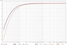
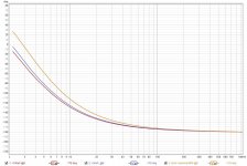
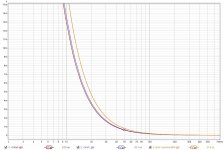
1st diagram is freq response at low end. 2nd diagram is phase, 3rd is group delay.
Light brown is with the stock 22uF.
Blue is with an added 50uF (total 72uF).
Red is with an added 100uF (total 122uF).
George
Now the low bass can be improved by increasing the capacitance of the two 22uF bypolar electrolytic caps found close to the multipin connector on the main board. The easy way is to parallel some bypolars by soldering them across the pins of the existing caps at the underside of the board.
I didn't have bypolars. I tested with back to back polar electrolytics.
1st diagram is freq response at low end. 2nd diagram is phase, 3rd is group delay.
Light brown is with the stock 22uF.
Blue is with an added 50uF (total 72uF).
Red is with an added 100uF (total 122uF).
George
Attachments
Last edited:
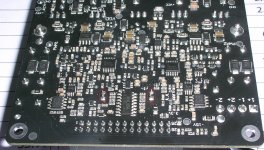
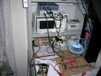
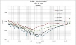
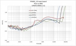
Some measurements on the FFA001_V3 main amplifier board (no buffer board).
Amplifier in stock form (one channel only) driven single ended from the line-out of an EMU 0404 soundcard.
Load is a home made set of dummy load power resistors.
Vout goes to Jan Didden's Autoranging attenuator (manual mode) and from there to soundcard's input.
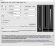
Software is the excellent REW. The measurement files are exported to MS Excel for convenient and uniform presentation.
Amplifier in stock form (one channel only) driven single ended from the line-out of an EMU 0404 soundcard.
Load is a home made set of dummy load power resistors.
Vout goes to Jan Didden's Autoranging attenuator (manual mode) and from there to soundcard's input.
Software is the excellent REW. The measurement files are exported to MS Excel for convenient and uniform presentation.
Attachments
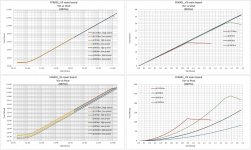
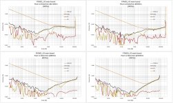
Vout, Pout, gain, linearity.
44.1kHz sampling rate. A passive 33.7kHz 12dB/oct LP filter btn dummy load and AR
44.1kHz sampling rate. A passive 33.7kHz 12dB/oct LP filter btn dummy load and AR
Attachments


Last edited:
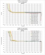
Step Level distortion.
44.1kHz sampling rate. A passive 33.7kHz 12dB/oct LP filter btn dummy load and AR
44.1kHz sampling rate. A passive 33.7kHz 12dB/oct LP filter btn dummy load and AR
Attachments
Last edited:
- Home
- Vendor's Bazaar
- 2x150W Amp module for sale