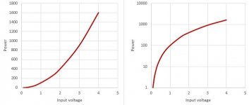
Datasheet plots of input voltage, current, distortion and power output have a curious nonlinearity at the origen of the input voltage curve. The plot usually rises steeply and then bends slowly to form a (somewhat) straight line for most of the graph. This implies that power output is not linear for very low input levels, becoming (more) linear only at higher input voltages.
What is the reason for this behavior? It is present for different tubes, different manufacturers, so seems intrinsic. But I don't recall reading any mention of this effect.
It would seem to imply a kind of compression for very small signals.
Charging up a capacitance comes to mind, since there is linearity at higher levels.
Am I just not using the right words and search terms?
Mr Langford Smith showed several decades ago that a pentode properly loaded and biased is capable of more amplification with lower distortion. But I don't know why audiophiles dislike pentodes.

Danny42c,
1. Are you talking about the family of plate curves, versus grid to cathode volts?
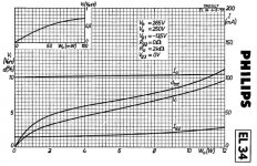
In the attached example pentode .pdf file, you will find that for the first 75 Volts on the plate, the current rises rapidly when the grid is from 0 Volts, to a few volts negative.
The slope of that part of the curves is vertical. That is the Ohmic region of the plate curves. Plate impedance, rp, is low there.
At higher plate voltages, about 200V or more, the plate curves are horizontal, plate impedance, rp, is higher there.
Generally, that is normal for both Pentodes and for Beam Power tubes.
Does that answer your question?
2. You said: "audiophiles dislike pentodes"
Many do, and many do not dislike them.
3. You asked about linearity?
From 0 volts to -2V grid, there is a very Large change of plate current.
From -18V to -20V grid, there is a very Small change of plate current.
Making a pentode, beam power tube, or a triode be linear requires careful design of the range of voltages and currents set.
Of course, a lot of designers use various modes of negative feedback to improve that linearity.
1. Are you talking about the family of plate curves, versus grid to cathode volts?
In the attached example pentode .pdf file, you will find that for the first 75 Volts on the plate, the current rises rapidly when the grid is from 0 Volts, to a few volts negative.
The slope of that part of the curves is vertical. That is the Ohmic region of the plate curves. Plate impedance, rp, is low there.
At higher plate voltages, about 200V or more, the plate curves are horizontal, plate impedance, rp, is higher there.
Generally, that is normal for both Pentodes and for Beam Power tubes.
Does that answer your question?
2. You said: "audiophiles dislike pentodes"
Many do, and many do not dislike them.
3. You asked about linearity?
From 0 volts to -2V grid, there is a very Large change of plate current.
From -18V to -20V grid, there is a very Small change of plate current.
Making a pentode, beam power tube, or a triode be linear requires careful design of the range of voltages and currents set.
Of course, a lot of designers use various modes of negative feedback to improve that linearity.
Attachments
Last edited:
In the attached example pentode .pdf file, you will find that for the first 75 Volts on the plate, the current rises rapidly when the grid is from 0 Volts, to a few volts negative.
The slope of that part of the curves is vertical. That is the Ohmic region of the plate curves. Plate impedance, rp, is low there.
At higher plate voltages, about 200V or more, the plate curves are horizontal, plate impedance, rp, is higher there.
Generally, that is normal for both Pentodes and for Beam Power tubes.
The part below 75 V (EL34) reminds of the Early effect in BJT's
Not being all too familiar with tubes, would it be possible to remediate it by cascoding the pentode, any limitations?
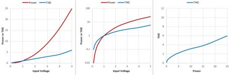
The distortion is directly proportional to output voltage, then rises as you approach clipping. But power is the square of the voltage, so the graph ends up looking curved when plotted against power. The tube isn't doing anything unusual. Here's some bogus data I plotted, all three graphs show the same data; the third one is power v. THD and looks just like the EL34 datasheet.The plot usually rises steeply and then bends slowly to form a (somewhat) straight line for most of the graph.
What is the reason for this behavior?
Attachments
Last edited:
Ultimate Thule,
Similar curves, used over a similar portion of those curves . . . cause similar modification of a pure sine wave.
BJT, MOSFET, Pentode, Beam Power, and JFET . . . it does not matter.
Cascode stages, a couple of important parameters:
The Miller Effect of the bottom device in the cascode is greatly reduced (BJT, MOSFET, JFET).
The output impedance of the top device is very large, relative to a non-cascode stage.
How well cascode stages perform depends on:
The circuit values around the cascode input and output,
The amplitude of the signal,
The frequency range of the signal.
"There are hundreds of engineering solutions, many of them work very well, but only if they are implemented properly".
Have fun Cascode-ing, or use any of the many other non-cascode circuits.
I do not use cascode circuits in audio.
Cascode stages have many important characteristics that are very useful for RF frequencies.
Perhaps the most commonly used cascode stages were dual triodes in VHF TV tuners, Millions and Millions.
Just my opinions
There's lots of plots. Show us the plot you mean. (Grab the image, or give us a link to image or PDF or what have you).Datasheet plots of input voltage, current, distortion and power output have a curious nonlinearity at the origen of the input voltage curve.
Using Beam Power and Pentodes in Cascode might be redundant,
But it will cause the top plate impedance, rp, to be even higher than that of a single Beam Power or Pentode.
That may, or may not, be an advantage, depending on how you use it.
I was not rooting for, and I was not rooting against . . . using cascode Beam Power or Pentodes.
I was only listing the effects.
Well, I forgot to mention the need for double the B+ (unless you choke load, resistor load, or CCS load the bottom plate, and capacitor couple to the top cathode, which needs another choke, resistor, or current sink. In that case there is no need for double the B+ voltage, but you did have to add at least 3 parts.
It can be done, but why?
There was a good reason to use that coupling cap method on the 30MHz If amplifier of a 10GHz radar.
Cap coupling the bottom tube and top tube works cheaply and easily for RF frequencies.
Lower B+ for the rest of the radar receiver, including the little 10 GHz Klystron local oscillator.
The O.P. obviously refers to the "Transfer Curve".There's lots of plots. Show us the plot you mean. (Grab the image, or give us a link to image or PDF or what have you).
plate current vs grid voltage at constant plate to cathode voltage.
Whether triode, pentode, small signal, power tube, even SS, they all start "curved" at low currents and end almost as a straight line at or beyond max dissipation.
quote o.p: " This implies that power output is not linear for very low input levels, becoming (more) linear only at higher input voltages.
What is the reason for this behavior? It is present for different tubes, different manufacturers, so seems intrinsic. But I don't recall reading any mention of this effect." unquote o.p.
At 0VDC, the device has no external energy input, and cannot amplify.
There must be a transition region between the 0V and nominal operation.
There must be a transition region between the 0V and nominal operation.
sorento,
I think the description in Post # 1 is not very descriptive.
That would mean that which curve(s) he is talking about is not obvious.
The transfer curve you mentioned does not give power out, and does not give distortion out.
Get a pre-1970 ARRL Radio Amateur Radio Handbook. If you are lucky your local library did not throw them out.
Learn about resistance, current, voltage, Kirchhoff, Norton, capacitance, inductance, reactance, resonance; then about fields.
Read up on tube theory, starting with a tube diode and the saturation curve, etc.
Step by step, triode, tetrode, pentode/beam power tubes.
Or read the US Navy electronics training courses mentioned in Tubes / Valves threads
Then, . . . start tinkering.
Many complex things are neither quickly nor easily understood.
Albert Einstein was still working on the Unified Field Theory when he passed away.
Last edited:
- Home
- Amplifiers
- Tubes / Valves
- Pentode nonlinearity at low levels of drive voltage