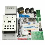
The circuit boards are included, and while there is nothing wrong with them per se, I prefer to wire point-to-point for the audio portion of the circuit. I am planning to purchase replacement sockets that will screw directly onto the chassis with no circuit board underneath, which shouldn't be a problem. I will use the PCB for the power supply though.
I did note that the manufacturer didn't put a support standoff and screw on either side of each tube to support the board when inserting and removing tubes. That would have been a nice touch, but this is an amplifier with a very compact footprint, so I suspect there just wasn't room to use 12 supports around the tubes.
The kit is still sitting in my shopping cart. I haven't checked out yet. I am trying to find out what (if any) instructions are provided these days since xraytonyb built his 4 years ago, and the kit seems to have changed since then by eliminating the loudness circuit and switch, which was the primary modification that xraytonyb did, so that's good. Unfortunately, communicating with the sellers in China is difficult right now. Most are out of the office for several weeks. While instructions other than a schematic are not really required, they do help sometimes. The kit that xraytonyb bought came with 36 pages of photo instructions, which was a nice touch.
Attachments
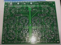
Yes, the missing mechanical support of the tube holders isn't good at all. Anyway, the biggest evil with this PCB are the LED's inmidst the holders. Typical Chinese bling-bling bells and gongs and as unneccessary as a hole in the head. Of course, no one needs to populate them if he doesn't want to.
Best regards!
Best regards!
Yes, xraytonyb omitted the LEDs under the tubes. He just left off the LED and the SMD resistors for them. The latest McIntosh 275 has LEDs under the tubes too. $6,000 each. So it's not just China. If I were going to use LEDs I would at least want them to be green or blue. 
Since these are small tubes and a very small circuit board, and it is fiberglass, the lack of extra supports for the PCB might not be a big issue so long as one is aware of it and is careful when inserting and removing the tubes. They are easier to pull than big power output tubes. I suspect some sort of electrical cleaner/lubricant would facilitate insertion.
Since these are small tubes and a very small circuit board, and it is fiberglass, the lack of extra supports for the PCB might not be a big issue so long as one is aware of it and is careful when inserting and removing the tubes. They are easier to pull than big power output tubes. I suspect some sort of electrical cleaner/lubricant would facilitate insertion.
Attachments
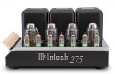
The new MC275 is just a bling-bling amplifier that hasn't too much in common with the genuine design (e. g. bifilarly wound OT primaries on one bobbin instead of trifilarly on two bobbins...). Appears that it's being fabricated in China alsoThe latest McIntosh 275 has LEDs under the tubes too. $6,000 each. So it's not just China.
.It also applicates to the new MC3500 Mk II.
Best regards!
bifilarly wound OT primaries on one bobbin instead of trifilarly on two bobbins
Where did you find that information? Do you have links?
Chinese new year is over today (I think). Sellers in China told me they would be back in office tomorrow, so maybe I can get more information about the current version of the little 6P14/EL84 integrated amplifier this week. I suppose it's not really an "integrated amplifier." I think it's more accurately described as a power amplifier with a "passive preamplifier" (a/k/a volume pot) stuck on the front. Correct me if I'm wrong. It seems that a true integrated amplifier would have 2 more tubes on the input?
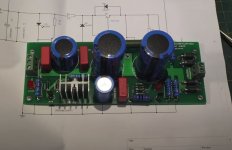
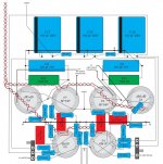
After drawing the circuit and parts to scale, I doubt my ability to wire it point-to-point. The area inside the chassis is just too small. The small footprint is one of the big appeals to me though, along with the fact that it won't heat up the entire room like my Stereo 70 used to do. That amp runs hotter than the pure class A, 2x50W, Threshold transistor amp that I had, which threw off a whole lot of heat. The heatsinks down both sides would burn your hand after a few seconds. I think it weighed about 50 pounds and the heatsinks were enormous. I'm not sure why the Dynaco ST-70 version II runs so doggone hot. It also eats up EL34 output tubes.
After drawing the circuit and parts to scale, I doubt my ability to wire it point-to-point. The area inside the chassis is just too small. The small footprint is one of the big appeals to me though, along with the fact that it won't heat up the entire room like my Stereo 70 used to do. That amp runs hotter than the pure class A, 2x50W, Threshold transistor amp that I had, which threw off a whole lot of heat. The heatsinks down both sides would burn your hand after a few seconds. I think it weighed about 50 pounds and the heatsinks were enormous. I'm not sure why the Dynaco ST-70 version II runs so doggone hot. It also eats up EL34 output tubes.
Attachments
Last edited:
The new MC275 is just a bling-bling amplifier that hasn't too much in common with the genuine design (e. g. bifilarly wound OT primaries on one bobbin instead of trifilarly on two bobbins...). Appears that it's being fabricated in China also
All their products are manufactured in Binghamton, NY, including the chassis and transformers. Want to see one built?
Sorry, no link. I've read it in a German magazine about 30 years ago when they reviewed a then new edition of this amplifier. Anyway, you can see the trifilar vs. bifilar thing by a schematics comparison.Where did you find that information? Do you have links?
Best regards!
Perhaps it is biased wrong. What are the cathode currents?I'm not sure why the Dynaco ST-70 version II runs so doggone hot. It also eats up EL34 output tubes.
Tubes in the original Stereo 70 lasted a very long time.
Last edited:
Never,
If you aren't going to use the eye tubes your filament voltages might run a bit high, especially if your line voltage is high as well. I usually keep a few 0.05 and 0.025 ohm, 3 watt, WW resistors handy for these situations. Put one in series with each lead from the power trans to the tube filaments.
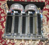
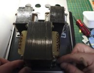
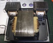
I skimmed Xray Tony's build videos a few years ago. One thing he did was rotate the orientation of the OPTs so their cores/laminations would be at right angles to the power transformer. (The kit instructions had them all aligned.)
Tony's grid stopper resistors are a good idea. You wouldn't need to do surface mounts like his if you don't want to. Just cut the traces as needed and put a 1/4 watt resistor between the tube socket pin and a trace with the a spot of mask scrapped off.
If you don't want to use the kit's gain/phase splitter tubes but don't want to spring for ECC85s, 12AT7s are kinda, sorta a 12 volt equivalent. You'd have to rewire the filaments though.
Good luck, S.
If you aren't going to use the eye tubes your filament voltages might run a bit high, especially if your line voltage is high as well. I usually keep a few 0.05 and 0.025 ohm, 3 watt, WW resistors handy for these situations. Put one in series with each lead from the power trans to the tube filaments.
I skimmed Xray Tony's build videos a few years ago. One thing he did was rotate the orientation of the OPTs so their cores/laminations would be at right angles to the power transformer. (The kit instructions had them all aligned.)
Tony's grid stopper resistors are a good idea. You wouldn't need to do surface mounts like his if you don't want to. Just cut the traces as needed and put a 1/4 watt resistor between the tube socket pin and a trace with the a spot of mask scrapped off.
If you don't want to use the kit's gain/phase splitter tubes but don't want to spring for ECC85s, 12AT7s are kinda, sorta a 12 volt equivalent. You'd have to rewire the filaments though.
Good luck, S.
Perhaps it is biased wrong. What are the cathode currents?
That I don't know how to measure. It has LED bias indicators on the front and two pots that you adjust so they are of equal brightness. I have no idea what level that sets the bias to, and I always have wondered about that.
I am working on the schematic though, which I finally found last night, but due to poor printing, some of the values are not legible. However, when I gutted and rebuilt it, I made a diagram and a list of which resistor was which, and I wrote down all of the values, so I can put clear values on the schematic.
The circuit board that came with the ST-70 series II was just terrible, as were the components, and every time a tube went bad, it burned out several resistors in a puff of smoke, and I had to replace them. As part of my overhaul, I used higher power resistors that have not burned out after 20 years of use and 10 years of sitting on the shelf. I used a piece of fiberglass board, which I had on hand from a hobby project, drilled it, and wired everything point-to-point underneath. Where I couldn't get the components to reach each other directly, I used silver wire that I bought from a jeweler. I upgraded the power tube sockets with what I could get at the time and upgraded their wiring as long as I was at it. I also had a machine shop make a new cover plate so I could upgrade and enlarge the power supply capacitors. That was about 30 years ago, and I haven't touched any electronics since. I have now forgotten most of what I used to know.
So, I got the Dynaco ST-70 series II off the closet shelf last night, after 10 years of sitting unused, in desperation for better sound than my 5-channel Outlaw Audio power amp, which I could barely move by dragging it across the carpet because it weighs 85 pounds. I can't lift or even move that much weight any more. Ah, the magic of tubes. The clarity. The depth. A piano that actually sounds like a piano for a change. Except for some static in the left channel, I was surprised to find that it still works without any issues, so far. Replacing the two 6GH8A driver tubes solved the static problem, which probably is dirty tube pins and sockets. The problem now is that the Emotiva A/V-surround processor that is feeding the Dynaco its pre-amp power has appalling 2-channel audio and the worst DAC I have ever heard in my life, so I'm using the analog out from a Sony DVD player, which is remarkably good with its Burr-Brown D/A chips (I looked inside).
For the sake of simplicity and low cost, I'd like to switch between an old Denon A/V receiver that someone is willing to donate to me (I love free - the price is right) and the little integrated amp kit that is the subject of this thread, so I don't have to change speaker wires, which with my speakers isn't so easy to get to.
Question: does anyone know whether I could leave both a tube amp and the Denon receiver connected to the speakers at the same time without messing up the sound or damaging anything? Only one would be powered on at a time. Or do I really have to buy/build a switch to go from one amp to the other?
One way or another, the Outlaw Audio amp and Emotiva A-V processor/preamp are getting replaced. I can't stand them any more.
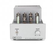
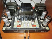
How could one of these amps (pictured) be SO MUCH better than the other? TUBES! The Outlaw Audio was $1,500 plus shipping, so not a cheap budget amp. I still have the receipt. I wish I still had a budget like that, but I don't. The stereo budget currently is almost $0, which is one of many reasons why I am looking at building the little tube "integrated" amp kit. At $309 delivered, it's cheap, can accept 2-channel directly from a decent CD/DVD player, it has a very small footprint, the component quality is good, the output that xraytonyb measured with his scope on the bench was clean, and its tubes are both small so they will not heat up the whole room and they are inexpensive. For all of these reasons I want to try the little "integrated" amp kit. It might be just what I need to downsize everything but still have tube sound.
Attachments
Never attempt to connect more than one amplifier channel to a single speaker at one time.
That would surely damage one or both of the amplifiers.
If a switch is used to select which amplifier is connected to the speaker, make sure it is a break before make switch.
Both conductors of each speaker wire should be switched at the same time.
That would surely damage one or both of the amplifiers.
If a switch is used to select which amplifier is connected to the speaker, make sure it is a break before make switch.
Both conductors of each speaker wire should be switched at the same time.
Never,
If you aren't going to use the eye tubes your filament voltages might run a bit high, especially if your line voltage is high as well. I usually keep a few 0.05 and 0.025 ohm, 3 watt, WW resistors handy for these situations. Put one in series with each lead from the power trans to the tube filaments.
I skimmed Xray Tony's build videos a few years ago. One thing he did was rotate the orientation of the OPTs so their cores/laminations would be at right angles to the power transformer. (The kit instructions had them all aligned.)
Tony's grid stopper resistors are a good idea. You wouldn't need to do surface mounts like his if you don't want to. Just cut the traces as needed and put a 1/4 watt resistor between the tube socket pin and a trace with the a spot of mask scrapped off.
If you don't want to use the kit's gain/phase splitter tubes but don't want to spring for ECC85s, 12AT7s are kinda, sorta a 12 volt equivalent. You'd have to rewire the filaments though.
Good luck, S.
Thanks. I will test the filament voltage after building the power supply board. I'll have to go back to see if xraytonyb measured it.
I noted the grid stopper resistors, but the revised version, 4 years later, seems to have removed all of the loudness circuitry and switch that xraytonyb removed. I don't know if the grid stoppers are there now, but I did note that they should be added if they are not. I liked that he used the ALPS pot. I have no idea how much one costs or what I might find in the revisedkit.
My voltage currently is 121V.
The ECC85 isn't too expensive when the included tubes die, or I could stick with the Russian 6N1P replacements if they don't sound bad.
1) Never attempt to connect more than one amplifier channel to a single speaker at one time.
That would surely damage one or both of the amplifiers.
2) If a switch is used to select which amplifier is connected to the speaker, make sure it is a break before make switch.
Both conductors of each speaker wire should be switched at the same time.
1) Even if both are off?
2) Even if both are off?
One thing he did was rotate the orientation of the OPTs so their cores/laminations would be at right angles to the power transformer. (The kit instructions had them all aligned.)
One comment indicated that the orientation change did not matter as the coils were already 90 degress to each other, and the magnetic field is determined by the coils, not the laminations? By rotating them, I don't see that it changed anything as far as power transformer vs. output tranformer magnetic fields, but it might have resulted in better isolation of the two output transformers from one another. Thoughts anyone? Like I said, after 30 years of not doing this, I have forgotten a lot of things. Pics attached.
I do want to thank everyone here for being so helpful. My memory of electronics needs some serious refreshing, and I never was an "expert" anyway.
Next thing I need to do is refresh my memory of all of the different abbreviations for things like Va, Vg, S, μ, B+, etc. and what effect each one has. There is no end to the list of abbreviations used.
Attachments
Referring to this earlier post, that looked like quite a neat drawing tool for doing the layouts - which one is it?Chinese new year is over today (I think). Sellers in China told me they would be back in office tomorrow, so maybe I can get more information about the current version of the little 6P14/EL84 integrated amplifier this week. ...
It may be that you should alter the wiring layout for the filaments. Is there one heater winding? There is a very useful sticky thread on this forum for pointing the way. The heater wiring should be as out of the way as possible, skirting around other wiring so hum is not induced anywhere. Usually the tubes most sensitive to hum are the end of the heater wiring.
When you do start this project it is worth doing the heater wiring first then powering up to test continuity, then the rest of the point to point wiring. Can be tricky to rectify the heater wiring later. I managed to cause a short one time because the soldering heat melted the insulation at the twist in the wiring near the heater pins, so nowadays I check for lack of continuity between the heater pins before 'firing up' (hopefully metaphorically).
Yes and Yes, since turning the system on and off at the mains does not isolate the outputs, so all of the electronics in each system is shared. There are some sorry tales of ruined solid state amplifiers for this reason if you search for them.1) Even if both are off?
2) Even if both are off?
Since the tube amp needs a load on its output transformer you would also have to have a dummy load that is switched out when the speakers are connected. If you are thinking that part is only applicable if the tube amp is on, then it is quite likely you might switch it on with the switch in the wrong position, so it is shrewd to consider the potential pitfalls.
Sure. But it will be in the low digits percent range and won't hurt at all. Undervoltage of the same percentage will be of some more concern.If you aren't going to use the eye tubes your filament voltages might run a bit high,
Best regards!
Kay, Maybe I'm just being over-cautious, but when the filament voltage regularly runs over 6.3, I get a little antsy. Granted, most specs rate 6.3 volt filament tubes from 5.7 to about 7 volts but much above 6.5 is pushing it, IMHO.
OldHector, I also like to check filament light-up before applying B+. Over-caution again.
Never, You won't get an accurate read on filament voltage until all tubes are in and B+ is applied (the PT is loaded down). ALSO NOTE: The Russian 6N1P is, from all reports, nothing like Chinese 6N1. Some, mostly eBay sellers, would have you believe that the Russian 6N1P is similar to and a drop-in replacement for the 6DJ8 family of tubes. IT IS NOT!
Best luck,
Steve
- Home
- Amplifiers
- Tubes / Valves
- 6P14/EL84 amplifier kit building questions - before I build - maybe during if I do