Hello everyone,
I need help. I am trying to restore a representative of the legendary NAD 3020A
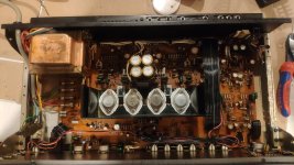
I was able to restore it to working order. I replaced all of its electrolytic capacitors, cleaned it thoroughly (it was very dirty), greased all of the trim pots, and replaced the volume gain pot.
The amp worked well and I was happy with the sound quality.
When we tried to test it with some new KEF speakers of a colleague of mine, when increasing the potentiometer to 40-50%, a flame started coming out from inside.
After inspection and measurement - the two final transistors (2N3055 and MJ2955) and the pre-final transistors (2SD669 and 2SB649) were blown on one channel, the resistor 651 was also burnt.
I have replaced the above components and now when I turn it on there is no flame, but that is only because I have not connected a load to the output. On this same channel I currently have +30 Vdc, (while on the other I have 0 Vdc). Now if I turn any speakers back on they will either burn out or burn out the transistors again or both. Fortunately, the colleague's expensive speakers are sound.
Please advise where to look for the problem. Apparently something is keeping the end transistors fully open, but I don't know what causes them to be in that state.
After I restore it, I might think about a slight upgrade with speaker protection.
I need help. I am trying to restore a representative of the legendary NAD 3020A
I was able to restore it to working order. I replaced all of its electrolytic capacitors, cleaned it thoroughly (it was very dirty), greased all of the trim pots, and replaced the volume gain pot.
The amp worked well and I was happy with the sound quality.
When we tried to test it with some new KEF speakers of a colleague of mine, when increasing the potentiometer to 40-50%, a flame started coming out from inside.
After inspection and measurement - the two final transistors (2N3055 and MJ2955) and the pre-final transistors (2SD669 and 2SB649) were blown on one channel, the resistor 651 was also burnt.
I have replaced the above components and now when I turn it on there is no flame, but that is only because I have not connected a load to the output. On this same channel I currently have +30 Vdc, (while on the other I have 0 Vdc). Now if I turn any speakers back on they will either burn out or burn out the transistors again or both. Fortunately, the colleague's expensive speakers are sound.
Please advise where to look for the problem. Apparently something is keeping the end transistors fully open, but I don't know what causes them to be in that state.
After I restore it, I might think about a slight upgrade with speaker protection.
Attachments
The channel with the +30 volt output could have a shorted Q607 or open R647 or 649. Wont cause fire, but a problem nonetheless.
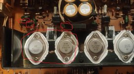
Be vewy vewy cawefuw hewe. Both of those MJ2955 are FAKE. A date code of 2006 is inconsistent with the old Motorola logo. No idea about the ST 3055 - they are often faked and hard to tell without testing. If you got burned by one, it’s possible to be burned by another if you’re getting them outside normal distribution. The only one I’d trust to be real without investigation is the old aluminum Motorola. Those simply predated all the faking.
Be vewy vewy cawefuw hewe. Both of those MJ2955 are FAKE. A date code of 2006 is inconsistent with the old Motorola logo. No idea about the ST 3055 - they are often faked and hard to tell without testing. If you got burned by one, it’s possible to be burned by another if you’re getting them outside normal distribution. The only one I’d trust to be real without investigation is the old aluminum Motorola. Those simply predated all the faking.
Thanks for the opinion.
I will check those items you mentioned.
And about the transistors:
I got this amp in a miserable condition - it was flooded with some sticky liquid, only a loud hum could be heard at the output...it was in very bad condition.
With a basic cleaning and washing the circuit board with circuit board spray I was able to bring it back to life. Because I quite liked the sound that comes out of it, I decided to update it and therefore I made a full recap of it.
I also decided to change the final transistors with supposedly original ones (at least the models should be the same as the original circuit), but after the change I did not do any kind of calibration.
Some people say that since the final ones are changed, it should be measured in rest mode, what is the voltage at their base and equalized as much as possible and it is about 0.55V (with a change of resistors to the pre-final ones for example) .
Anyway, after the recap and the replacement of the final transistors, it whistled, although I hadn't listened to it for a long time or very loudly.
I bought the transistors themselves from the USA and they were supposedly delivered from Mexico via ebay. Apparently everything on the market is fake now. For this reason, most of the parts I buy are second hand and removed from old amps. Unfortunately I couldn't find a second hand MJ2955 anywhere.
How can I check / measure whether a transistor is original or not?
And the transistors from Mexico themselves doubted me when I received them, because the location between the body of the transistor and the two legs of the transistor was blue, and I think that none of the old ones have such blue insulation.
Step 1. Don't buy transistors on ebay. 99.9% are fakes.
One way to detect fakes is Iceo test. Put 24 v c to e (or - 24 for pnp) measure I (current) with a DVM. Then if you have a PS that big, 60 v. warning >24 v from one hand to the other can stop your heart. Use one hand and clip leads. Series 100 ohm resistor may be necessary to preserve fuse in meter on I scale. Iceo should be microamps below Vceo rating of transistor. Fakes that pass Iceo test may violate SOA spec which is way harder to test.
I would use On Semi MJ21193 MJ21194 from newark or digikey for TO3. Or MJ21195 MJ21196 depending what is in stock. Looks like latter today Newark US. 93/94 today Farnell in UK. I also trust digikey & mouser, although mouser won't tell you service life of e-caps. I'm closest to newark in SC.
Then to determine whether amp is repaired, put a 60 v incandescent lamp series the AC line. I have my edison medium base inside a steel case with a circuit breaker series the lamp in case a wire pops loose from the screw & strikes the case. Better blow the breaker than hit your hand with mains AC or set fire to your work table. Those screw bases are made for solid core wire, which does not fit circuit breakers etc. Mesh cover on box lets you see if lamp is lit (fault). Lamp should flash then go out. Leave speaker disconnected until DC on speaker terminal is gone, and idle current on O.T. is 15-60 ma. 20 ma idle current is best for TO3 on adequate heat sinks. May need realignment of temp sense transistor to achieve proper idle current. Do any final testing with trash resale shop/junkyard speakers, or put series bipolar >2000 uf capacitor series speaker. I use salvage FM radio for signal source for final test or to detect AC problems after DC voltages are proper.
If series lamp stays lit, look at voltages on the suspect channel to see if they are reasonable or not. Use one hand, put DVM negative on speaker return line with alligator clip lead.
If any other transistors shorted, I would use On Semi BD140 for temp sense transistor, ON MJE15028/29 drivers, ON MPSA06/56 for input transistors. Match package on VAS. Watch the pinout on the input transistors, BC transistors are all over the map on pinout. Different brands are even different pinouts. On makes some different TO92 pinouts like bc556/557 bc550/560, bc639/640. If original input transistors EBC may need to buy TO39 case of some 80 v Vceo transistor.
Last edited:
From the devices I've seen, that ST is very suspicious too. ST discontinued the TO-3 2N3055 sometime back around 2013. Devices frombefore then also had 5 lines of date coding. And I agree with wg_ski that the "Motorola" 2N3055's are likely to be fakes too. In 1999 Motorola outsourced their semi line to ON semi, so the logo should at least have been ON, although it is just possible that the date code refers to an earlier time (1996 ?) but even then I think the date code would have been 96 - week.
Last time I looked ON semi still sell a TO-3 2N3055, so if you buy replacements make sure that you buy from a reputable dealer like RS or Farnell/Newark and that the devices are ON Semi. There may be some other manufacturers of genuine 2N3055's but hard to check.
The latest version of ON Semi's 3055 also has a better SOA than ST's and Motorola's early epi -base 3055, so it is probably a better device in disguise, although perhaps not meeting the full spec of that other device.
BC546-560 with flat down are EBC in the same format as TO-18/TO39; BC639/40 are BCE with the flat down. If these are the drivers then you might be able to use BD139-140 which are ECB with the tab down (all left to right). ST used to sell these too, last time I looked but it is hard to keep up with devices going obsolete now.
It seems as all TO-92's have explored the pin-out options, too,including 2N types, though many BC TO-92's with other pin outs seem to be obsolete.
In principle TIP3055/TIP2955 might be a replacement for the 3055 but I'd recommend the ON Semi TO-3's as having better SOA. ST's datasheet did not show the SOA on the one I have. Bourns (who once inherited the original from TI) shows a 30V breakpoint while ON semi 40V.
Last edited:
Why not putting them back?I also decided to change the final transistors with supposedly original ones
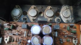
Please show a picture of the original output transistors if you still have them.
This is one of my options - just to return the old ones back.Why not putting them back?
Please show a picture of the original output transistors if you still have them.
I'm uploading a photo of what was on the board before I grabbed the soldering iron
Attachments
Known good transistors is the biggest problem with repairing these amps.
The other problem is the design - it’s much more finicky than it ought to be because it is emitter-resistor-less. If it wasn’t for that, fake output transistors wouldn’t even be a problem. It doesn’t require a massive SOA - I’ve seen receivers from that era with +/-30 volt supplies using 4 amp TO-220’s. It only takes double that to handle 4 ohms, and by then the supply is dropping. Adding 10 ohm base stoppers to the outputs is prudent if you know what you’re doing enough to do it. That basically turns a modern 2N3055 into the equivalent of a 1970’s model.
If you’re having to buy NEW and pay premium price, the best units to use are MJ15024/5. These have enough internal ballasting where they CAN operate emitter-resistor-less safely on this low a voltage. For this reason preferred over 2119x series in this application. Also enough SOA to handle speaker wires being shorted momentarily. Add 22 ohm base stoppers to these (these have more gain at 8A than 3055’s) and it will be pretty bulletproof.
If you are replacing drivers, you’ve just got to have real ones, close to the originals. I would be using Fairchild/ON A1220/C2960 (or is it 2690? - Too lazy to go out to the shop and look at the bin). Second-source versions of the originals supposedly are good - but only if you get them from some place like Profusion where they actually screen for fakes.
I think that puting back the previous transistors will not decide my problem and the +30V still be on the output.
It that is true, in the USA you have to buy ksc1220 ksc2690 . There are nothing but 2sa** 2sc** at any major distributor. in USA, other sources are fakers. I admit ECB TO126 with heat sink down is weird, but I could install separate heat sinks which cost $1on MJE15028/29, and install them backwards.If you are replacing drivers, you’ve just got to have real ones, close to the originals. I would be using Fairchild/ON A1220/C2960 (or is it 2690? -
I don't see the fascination with 2n3055/mj2955. There were homotaxial RCA 2n3055 sold until about 1980, but there was never a homotaxial mj2955. Motorola was always epitaxial. The homotaxials had a little emitter resistance that made them okay with no emitter resistor at low power. surplussales.com was selling allegedly homotaxial 2n3055 last year, but the MJ15024/25 are available at newark+digikey+mouser nearly all the time. Frankly I'd cut the output transistor emitter trace to the other transistor and insert .33 ohm 5 w resistors, standing up, but that takes some manual skill. Also takes a #51 drill in a pin vise to drill the holes.
Profusion.com is a data service. May as well buy transistors from the sheik of Araby himself, have them delivered by magic carpet. Profusionplc,com from the suffix is obviously not in North America.
As for the DC out on speaker, follow instructions about AC supply resistance in post # 5. Then with the device under test not burning parts, look for the source of the wrong DC voltage with a DVM. Make corrections at the source.
Last edited:
Why use hometaxial 2N3055's?
Modern ones are epi base of some form and have better frequency response. They are a better match to the MJ2955 than RCA devices were.
I'd not recommend mixing the two even if you could get hometaxials. I'm pretty sure the 3020 would have used epi devices in a complementary output stage.
Modern ones are epi base of some form and have better frequency response. They are a better match to the MJ2955 than RCA devices were.
I'd not recommend mixing the two even if you could get hometaxials. I'm pretty sure the 3020 would have used epi devices in a complementary output stage.
I take it that the 3020A no longer uses the 2N6553/6 driver transistors. Those were TO-202 which did not last long on the market. If the revised circuit uses KSC2690's then they have the same TO-126 package/pin-outs as BD139/BD140 which I suspect would also work in a 30 (up to 50) W circuit. I don't see the drivers in the photos, I assume the single TO-126 device is the bias stabiliser.
If the drviers are not on the main heatsink I would suggest if you do need to replace older 6553/6 with BD139/140 (or the KSC/KSA) put those somewhere on the heatsink too if you can find room and run lead wires back to their position on the PCB - as long as these are not longer than a say 5cm I would not think that would be a problem, but it is hard to say without trying it.
If the drviers are not on the main heatsink I would suggest if you do need to replace older 6553/6 with BD139/140 (or the KSC/KSA) put those somewhere on the heatsink too if you can find room and run lead wires back to their position on the PCB - as long as these are not longer than a say 5cm I would not think that would be a problem, but it is hard to say without trying it.
Last edited:
D669/B649 drivers were used when the TO-202’s went AWOL. Unfortunately, the original Hitachi parts are NLA as well now, but still highly sought after because they have the lowest Cob of any of the standard driver pairs. There is a second source now, probably UTC. Unfortunately, finding a real one of those is hit or miss. Far easier to use the Fairchild pair from Mouser. They are higher fT and lower capacitance then the BD139/40.
Hometaxial 2N3055s did have a higher parasitic BASE resistance, aiding in thermal stability. Even when used with epi PNPs. This is where the ”Homotaxial” cult came from. Motorola “PowerBase” varieties had some internal ballasting for the multiple emitter fingers so that gives some thermal feedback. MJ15024 was simply the biggest of that family. The newer 21194 used a new process which didn’t need as much added internal resistance so I’m not sure I’d trust it to be better here. What was really needed to insure thermal stability was to minimize junction to heat sink thermal resistance - to get the thermal bias spreader as close to the junction temps of the outputs as possible. Hence, using TO-3s instead of something smaller. Using metal 250W devices (for lowest junction to case and case to sink resistance) with some internal ballasting, seems to be the best approach. Aside from just adding emitter resistors to the board.
When you have known good drivers and outputs in there then you can diagnose why it’s stuck to the rail.
Last edited:
Agree. Without emitter resistors thermal feedback is more critical. Though I would recommend adding emitter resistors to assist. It seems unusual for output stages to omit these, exposing them to a risk of greater instability.
I apologize for the slow response, but with a wife and 2 small children at home, it is very difficult to find a hobby 🙂
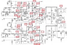
This morning I measured quite a few voltage values on both channels.
As can be seen, there are very serious deviations of the damaged channel compared to the normal one.
This morning I measured quite a few voltage values on both channels.
As can be seen, there are very serious deviations of the damaged channel compared to the normal one.
Attachments
i would suggest you have or have had a faulty output stage-you shoudl replace these, but only with ones from a reputable supplier(not ebay)I apologize for the slow response, but with a wife and 2 small children at home, it is very difficult to find a hobby 🙂
This morning I measured quite a few voltage values on both channels.
As can be seen, there are very serious deviations of the damaged channel compared to the normal one.
these are good and can be trusted
https://www.cricklewoodelectronics.com/
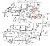
Check Q601 as the voltages are being pulled toward the neg rail
Q605,607 and the driver 611, these are possibly faulty, i replace these frequently when the output goes, it might not be but they should be checked
Also check R637
also change VR5 as these are very poor pots and are always a bit flaky
only the multiplier is on the heatsink on this model
I would pull Q617 & Q615 to take voltages without the problems. These voltages are with the 60 w light bulb in series with the AC line, correct? rail voltages look suspiciously high. New parts could keep blowing if you don't limit the energy of the faults.
Reason for taking voltages without the outputs, you want to buy the other blown parts in the same $10 box as the MJ15024/25 recommended for outputs by wgski.
I would definitely look at voltages both ends of D601, also junction R670&R671, also junction C601C603R607. See if adjusting pot VR605 can pull front end voltages much closer to normal.
I you are in USA I see no reason to import parts from UK, IE cricklewood. Customs sometimes takes 8 weeks. Cricklewood didn't have MJ**** anyway. Newark+digikey+mouser ship real parts, don't stock the fakes.
This is a hobby for me too. Work at your own pace, in the winter I'll be watching here. til May anyway.
Last edited:

The voltage at the base of Q601 is too high. That is what is causing it to stick to the rail. Check the input stage bias stack D603 and D601, and all associated resistors for opens or cold solder joints. This is an unusual arrangement - so that a singleton input stage (instead of a diff pair) can be used. It’s touchy, with multiple points of failure. Since the current thru that circuit is limited by a 22k resistor it’s unlikely to have burnt anything out - so an open resistor or diode may look fine. Don’t make that assumption on this amp - think of how a government contractor would bid it and what resistors they’d use.
And as an aside, if you do use MJ15024 outputs on this thing - immediately after fitting them, short Q609 collector to emitter for the first test. The dies in those are larger (which is actually good if you’re looking to improve thermal stability), but that will usually cause the amp to power up OVERBIASED. Not usually a big deal if there is a pot you can set to turn it to the minimum for a first time power up. But they cheaped out and used fixed resistors - which you will have to adjust once you’ve verified that nothing will cause fire. You start with R641 out of the circuit, and trim from high to low value to get the bias right. Or install a cermet pot. With it completely OUT the bias may still be high requiring further adjustment. Technically using the larger, lower Rth outputs is the right thing to do, but they didn’t make it easy.
And as an aside, if you do use MJ15024 outputs on this thing - immediately after fitting them, short Q609 collector to emitter for the first test. The dies in those are larger (which is actually good if you’re looking to improve thermal stability), but that will usually cause the amp to power up OVERBIASED. Not usually a big deal if there is a pot you can set to turn it to the minimum for a first time power up. But they cheaped out and used fixed resistors - which you will have to adjust once you’ve verified that nothing will cause fire. You start with R641 out of the circuit, and trim from high to low value to get the bias right. Or install a cermet pot. With it completely OUT the bias may still be high requiring further adjustment. Technically using the larger, lower Rth outputs is the right thing to do, but they didn’t make it easy.
- Home
- Amplifiers
- Solid State
- NAD 3020 A - HELP to repair