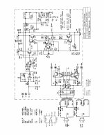
Trying to troubleshoot this GK amp (schematic attached).
Found three blown transistors (Q2, Q3,Q7) and replaced them. All other transistors seem to test good. Replaced the filter capacitors.
When the amp is powered on, it produced a loud hum at 120hz. There is 48v DC voltage on the speaker output. This would indicate blown power transistors (Q4 & Q8) right? I had a replacement for Q8 and put that in (no change) and Q4 also tests good.
What else can this be, given the voltage on the speaker out? I ordered a replacement for Q4 but don't expect it to work since the incumbent tests good.
Attachments
Have you verified that the power supply, including the 15V regulators, works properly?
How about the output transistor emitter resistors?
How about the output transistor emitter resistors?
No, would appreciate if you can tell me how to check.Have you verified that the power supply, including the 15V regulators, works properly?
How about the output transistor emitter resistors?
Are the emitter resistors the 0.33ohm resistors in this schematic? I can't find a fault with them.
Are the supply DC voltages correct? Is the unregulated supply ripple voltage correct?
Do the regulated supplies have visible voltage ripple on their outputs?
If so, they may be dropping out of regulation.
If the voltage ripple on the unregulated supply is excessive, this can indicate
either bad capacitors, or high fault current in the output stage, etc.
Do the regulated supplies have visible voltage ripple on their outputs?
If so, they may be dropping out of regulation.
If the voltage ripple on the unregulated supply is excessive, this can indicate
either bad capacitors, or high fault current in the output stage, etc.
Are the supply DC voltages correct? Is the unregulated supply ripple voltage correct?
Do the regulated supplies have visible voltage ripple on their outputs?
If so, they may be dropping out of regulation.
If the voltage ripple on the unregulated supply is excessive, this can indicate
either bad capacitors, or high fault current in the output stage, etc.
No, would appreciate if you can tell me how to check.
I'm not sure I'm reading it right. It looks like a LF351N op amp and the schematic seems to say -8.1v on pin 6 (?)Is the DC voltage at the opamp output correct?
Mine does not seem to match that. If I have the right pin, I see -12v.
Start with what Rayma asked you.
DMM setting on Vdc greater than 100V, black probe on ground and red probe on: A +60Vdc / D -60Vdc /B +15Vdc/C-15Vdc.
If one of these values does not match, you have a problem elsewhere and mainly the +/-15Vdc.
DMM setting on Vdc greater than 100V, black probe on ground and red probe on: A +60Vdc / D -60Vdc /B +15Vdc/C-15Vdc.
If one of these values does not match, you have a problem elsewhere and mainly the +/-15Vdc.
I think my voltages are normal there. I am getting +15/-15v and about +55/-55v.Start with what Rayma asked you.
DMM setting on Vdc greater than 100V, black probe on ground and red probe on: A +60Vdc / D -60Vdc /B +15Vdc/C-15Vdc.
If one of these values does not match, you have a problem elsewhere and mainly the +/-15Vdc.
Yes that's the schematic I'm working off. Are you alluding to the difference between the 55/60 volts? What to conclude about that?
???
can you tell us what are the references of the original transistors? if you replaced them with the same references and if you are sure that they are not counterfeits?
It's a fairly old amp, high power so probably TO3 2n xxxx or mj xxxx for the outputs and the same for the drivers
It's a fairly old amp, high power so probably TO3 2n xxxx or mj xxxx for the outputs and the same for the drivers
no it's just so that everyone has direct access to the schematicYes that's the schematic I'm working off. Are you alluding to the difference between the 55/60 volts? What to conclude about that?
???

Yeah it was MJ15002 & MJ15001 originally. I tried replacing the 15002 with a 15004 to no effect.can you tell us what are the references of the original transistors? if you replaced them with the same references and if you are sure that they are not counterfeits?
It's a fairly old amp, high power so probably TO3 2n xxxx or mj xxxx for the outputs and the same for the drivers
Waiting for a new 15003 in the mail to replace original 15001.
Pictured here is the original condition before I replaced the filter capacitors. So left to right it's 15031 / 15031 / 15030 / TIP 31B / TIP 31B
I replaced the first and third of the above mentioned. If they are counterfeits - I don't know, they test good.
For this kind of gross problem you don´t need a scope ... yet; a multimeter is fine since we MUST stabilize proper DC values first.
2) build a lamp bulb limiter, with an around 40-50W incandescent bulb , you´ll probably find those which have an olive sized quartz lamp inside a larger "standard" glass bulb.
3) turn amp ON, NO SPEAKER OR ANY LOAD and start measuring.
First: +/-V rails , nominal +/-15V ones feeding U1, speaker out voltage.
4) this "functional voltages" reading is faster/better that painfully measuring parts one by one and praying you hit the jackpot 🙂
Post results, future suggestions depend on what you find.
PS: TO3 power transistors are VERY hard to find, almost out of production, and very much falsified, so buy ONLY from Mouser/Digikey/Farnell.
A meter can tell you they are fine ... because it only applies a couple Volts that is, but this GK amplifier uses scary +/-60V rails, so transistors must stand at least 130/140Vce , real world, to be safe.
Okay, those voltages you're referring to are the ones I reported above, I guess;For this kind of gross problem you don´t need a scope ... yet; a multimeter is fine since we MUST stabilize proper DC values first.
2) build a lamp bulb limiter, with an around 40-50W incandescent bulb , you´ll probably find those which have an olive sized quartz lamp inside a larger "standard" glass bulb.
3) turn amp ON, NO SPEAKER OR ANY LOAD and start measuring.
First: +/-V rails , nominal +/-15V ones feeding U1, speaker out voltage.
4) this "functional voltages" reading is faster/better that painfully measuring parts one by one and praying you hit the jackpot 🙂
Post results, future suggestions depend on what you find.
PS: TO3 power transistors are VERY hard to find, almost out of production, and very much falsified, so buy ONLY from Mouser/Digikey/Farnell.
A meter can tell you they are fine ... because it only applies a couple Volts that is, but this GK amplifier uses scary +/-60V rails, so transistors must stand at least 130/140Vce , real world, to be safe.
+55/-55 rails
+15/-15 (give or take 0.05) including feeding the op amp LF351N
Speaker output is showing 47vDC
It sounds like it's most likely that one other output transistor is blown although it shows readings on the multimeter. I ordered that from Mouser and will try it out next, in a few days.
I guess that's my original question- since it is showing that DC voltage on the speaker output, can that be anything else? All the parts are cheap on this amp so I don't mind if I have to replace everything one by one - it's just that the PCB is very delicate and impossible to solder on without lifting traces so I want to do nothing unnecessary.
Try to track down source of this voltage. Measure Vdc at Q4base then repeat for Q3b.There is 48v DC voltage on the speaker output.
Expect +0.65 and +1.3 respectively. In this case replace Q4.
Resistance check the emitter resistors R21, R24 0.33ohms, 5W large white on heat sink.
Okay, unfortunately, I seem to have +15v DC (and slowing rising) on both the base and emitter of Q4 and Q8.Try to track down source of this voltage. Measure Vdc at Q4base then repeat for Q3b.
Expect +0.65 and +1.3 respectively. In this case replace Q4.
Resistance check the emitter resistors R21, R24 0.33ohms, 5W large white on heat sink.
Q3 is showing +15vDC on all three base, collector, emitter.
R21 and R24 seem to be right, but my meter is not that precise below 1 ohm.
🙁
Assume voltages will continue to rise until the 47V reported on spkr line.Okay, unfortunately, I seem to have +15v DC (and slowing rising) on both the base and emitter of Q4 and Q8.
Q3collector "cannot" be +15Vdc, it's connected to the "+60V rail"Q3 is showing +15vDC on all three base, collector, emitter.
Certainly bad news Q3b is anywhere near +15Vdc.
Monitor +60V rail from power on, is stable, measure at Q3c or Q4c or D3 cathode.
Has C7 (220uf) been replaced, might explain the "15V and slowly rising"
Otherwise need to take a close look at Q2 b/c/e voltages to GND.
Possibly 2 faults one being C7 leaking which masks the initial fault...
- Home
- Amplifiers
- Solid State
- Troubleshooting blown GK amp; 120hz + voltage on output