I can't see minimum and maximum input voltages for the 5V supply when looking at the data for 5U4. This probably applies to all 5V rectifiers.
Does anyone know?
I ask because I have a transformer supplying 4.4V and I want to know if this is in the ballpark or not.
Also, what are the effects of under-voltage on a rectifier?
Does anyone know?
I ask because I have a transformer supplying 4.4V and I want to know if this is in the ballpark or not.
Also, what are the effects of under-voltage on a rectifier?
Usually the filament spec is +/- 10%.
Low filament voltage will degrade performance, causing a higher voltage drop, and higher impedance.
Low filament voltage will degrade performance, causing a higher voltage drop, and higher impedance.
So for 5V the lowest recommended is 4.5V. Not so far out. It actually sounds good. So maybe I'm OK?Heaters are always +/- 10% nominal voltage. 4.4V unloaded is a little few.

Probably OK if you are running them at lower than max current. The cathode has to run hot enough
to generate enough emmision of electrons to support the current demand of the tube.
If it does not, it will not fare well for the cathode.
to generate enough emmision of electrons to support the current demand of the tube.
If it does not, it will not fare well for the cathode.
It's a 4.5V transformer, 20VA. But the primary is 240V. It measures 4.4V working and in the socket.Usually the unloaded voltage on a transformer is 10% over, so could that be a traffo for a 4v filament tube?
The current required is 130mA at 303v. Not such a big load on it.
I may change it when I find a better one that fits the space it's in, but it sounds good ATM.
Try to use another rectifier with lower current requirement (little higher loaded filament transformer voltage).
5AR/GZ34 requiring only 5V 2A -albeit it's direct heating-.
5R4 rare, but available.
I would use -if I were you- 4V rectifier.
European RGN series, or my beloved (Tungsram) PV200-600.
5AR/GZ34 requiring only 5V 2A -albeit it's direct heating-.
5R4 rare, but available.
I would use -if I were you- 4V rectifier.
European RGN series, or my beloved (Tungsram) PV200-600.
Hmm - interesting lateral thinking. I had a GZ34 in previously which I took out because the 5U4 sounded better. It's my rectifier of choice.
I do have some 4V AZ12 rectifiers, but I don't think they sound any better than a 5U4 if I remember correctly from the last time I A-B'd them. Don't have any RGN - you were thinking RGN2004 which is an AZ12 substitute?
What's special about the Tungsram PV200-600?
I do have some 4V AZ12 rectifiers, but I don't think they sound any better than a 5U4 if I remember correctly from the last time I A-B'd them. Don't have any RGN - you were thinking RGN2004 which is an AZ12 substitute?
What's special about the Tungsram PV200-600?
Nothing special .... but reminds me of my youth. 😉What's special about the Tungsram PV200-600?
Whatever able to serve my #801 PSE (600V, even 200mA).
So I read somewhere, sometime, that out of spec voltage was tested and proven to dramatically shorten tube life by I forget who, but one of the old school major manufacturers. However, in real life, especially if you have vintage equipment that was designed for a mains voltage a good bit lower than what we have today, that's just not proven to be true.
As someone that builds a lot, and tests ramping up on a variac, I can tell you a 5U4 being directly heated makes a whole lot of B+ before you can even tell it's on from the heater glow. Literally it can look off and be making 50% or getting close of normal B+. So the low heater supply should be fine, but as was said, it will limit the max current.
There are more efficient rectifiers. 5AR4 was mentioned, but being indirectly heated, at under voltage, I think they might might actually perform worse with low out of spec heater voltage. But I haven't tested that, that is just my gut feeling from tube building in general.
And sometimes, it is just build with what you got? In your case, I'd at least rough build out the circuit and try it.
Results of a tube life study attached.
4,4V on the 5U4 heater seems too low to me.
But might be OK with a light load.
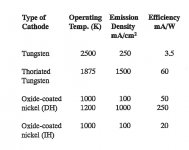
The cathode emission chart shews performance drops off quickly
as the cathode cools.
🙂
4,4V on the 5U4 heater seems too low to me.
But might be OK with a light load.
The cathode emission chart shews performance drops off quickly
as the cathode cools.
🙂
Attachments
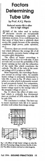
Not sure I follow. This is an over voltage assessment, on that graph, it looks like lower voltage might actually increase life. And as far as different materials, obviously that's a known, but irrelevant here? It doesn't apply, we're talking USA made tubes with comparable composition. And I do believe everyone has said that max current and performance will be affected and reduced. Which it will. Maybe trying to pull regular rated max current from a tube run under heated voltage would significantly reduce tube life, but I don't see that in these images.Results of a tube life study attached.
4,4V on the 5U4 heater seems too low to me.
But might be OK with a light load.
The cathode emission chart shews performance drops off quickly
as the cathode cools.
🙂
Ericsson's spent 6 years studying the effects for their SQ tubes, graph from page 10 ... since the cathode can recover would seem to be beneficial to underheat within bounds.

Ericsson LM Long Life tubes
Ericsson LM Long Life tubes
Diodes are a bit different - the datasheet shows a voltage drop versus plate current, and that plot extends out to 325mA. There is actually a lot more plate current available as the peak continuous rating for the 5U4 is 675mA, and the nominal (but not rated) peak transient current capability (during a power on surge) is upwards of 3A. So a diode's cathode has a lot of peak current capability, and for the rated X thousand hours of service life. Somewhat equivalently, if the cathode is not too old, the cathode can still pass substantial peak current level at a lower heater voltage. So the likely impact will depend on your amp's power requirements and whether the very peak of the diode current pulse gets up to a level where cathode emission is being limited - and even then it likely has little effect on the ripple and average current (sort of like a mains AC voltage waveform which is flat topped). Note that a common test for 'remaining life' of an output stage large bottle pentode is to notice when cathode conduction starts to drop off when heater voltage is lowered.
Yes, the 5U4 has got excellent reserves, and may tolerate underheating abuse for a while.There is actually a lot more plate current available as the peak continuous rating for the 5U4 is 675mA, and the nominal (but not rated) peak transient current capability (during a power on surge) is upwards of 3A. So a diode's cathode has a lot of peak current capability, and for the rated X thousand hours of service life.
Apropos the power-ON surge, there's one other thing worth mentioning there:
DH rectifiers warm up quite rapidly, but still, there is a point when the filament is «half-warm», where the emissive surface has uneven temperatures and hot-spots. IF the amplifier is drawing a large anode-supply current at this time, and/or the power supply capacitors are too large versus the available peak current from the PT (including the caps hiding behind filter-chokes) the DH rectifier can suffer an arc-over event: the hot-spot takes a local overcurrent, and vaporises the active-area of the hot-spot. This is easily witnessed if lower-rated rectifiers (5R4) are used. Once the tube has arced-over, it will happen again, ever-more easily.
Running more than 10% low on Vf will make the warm-up time longer, and the emissive capability gradually reduce. These consequences are liable to increase the risk of problems.
I would increase the voltage, if it were mine, alongside a quick check of the startup current (DC current load 2-5s after power-ON, PT resistances and capacitive load assessment).
Adding & removing a few turns on the secondary of a toroidal PT is easy; but use insulated solid wire for this application!
- Home
- Amplifiers
- Tubes / Valves
- 5U4 at over or under 5V?