Hi all,
This is my first post on this forum.
I am looking for wiring diagram (schematic, pictures) of Dali Oberon 7 crossover. I would like to build using proper components. I found one but without any details.
Thanks in advance.

This is my first post on this forum.
I am looking for wiring diagram (schematic, pictures) of Dali Oberon 7 crossover. I would like to build using proper components. I found one but without any details.
Thanks in advance.
Best bet is to take a photo of the board from both of the sides, and someone will draw a schematic for you. Inductors should be measured for inductance by pulling either of the 2 wires out of circuit. These sell for 1,200€ which is surprisingly expensive considering how cheap looking crossover is.
Last edited:
Thanks for reply. I can draw schematic by myself. I need only pictures on both sides with components values visible. I've got crossover from Zensor 7 and it looks alike. Oberon7 and Zensor7 have very similar cabinets and the same 7'' drivers.
I made upgrade for my Zensor 3 already. Sound is fantastic. Now I would like to build Oberon 7.

I made upgrade for my Zensor 3 already. Sound is fantastic. Now I would like to build Oberon 7.
Attachments
I have DALI Zensor 1, 5 & Vokal that have all been heavily modified and they now sound fantastic.
Here's a list of changes I made:
Crossover components replaced with higher quality parts having the same value.
Ports plugged with bungs as the sound emanating them was dreadful. (Put your ear to the port and you'll be shocked.)
All internal surfaces covered with self adhesive sound deadening foam.
Entire internal area of enclosures completely filled with Mundorf Twaron Angel Hair Wadding.
Entire area behind grilles covered with self adhesive sound deadening foam attached to the baffles and cut outs the size of the cones.
All metal parts of the drivers covered with self adhesive sound deadening foam.
All drivers grounded at three points: housing, both front and rear plates.
All drivers grounded at three points: housing, both front and rear plates.
Would you be willing to show us a picture or a drawing?
This is all I have at the moment. The ends of the copper wire are twisted together as tight as possible and there's a dab of Araldite to keep it in place.

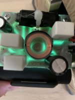
I thought I'd mention the crossover component upgrade. I only replaced the parts in the signal path to the speakers and ignored the components that sent the signal to ground. Here you can see them on a board beneath the original crossover. The yellow Mundorf Twaron Angel Hair Wadding is visible.

Hi,
I attached the schematic of the Oberon 7 Crossover
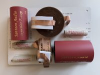
I don't have precise LCR meter to measure inductance but L1 somewhere 0.6-0.8mH the other parts are there. I have replaced R1 to Mundorf M Resist Ultra, R2, C1 Jantzen Standard Z-cap, C2 4,7uF Superior Zcap+.2.2uF Silver Zcap mix.

I attached the schematic of the Oberon 7 Crossover
I don't have precise LCR meter to measure inductance but L1 somewhere 0.6-0.8mH the other parts are there. I have replaced R1 to Mundorf M Resist Ultra, R2, C1 Jantzen Standard Z-cap, C2 4,7uF Superior Zcap+.2.2uF Silver Zcap mix.
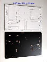
Thanks for the pictures of Oberon 7. Unfortunately, to read the value of L1, L2 you have to remove them from the PCB. I'll ask Dali, maybe they'll answer me.
In the meantime, I've upgraded Zensor 7.
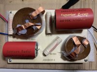
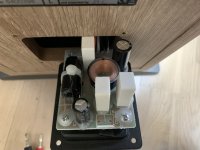
Since the elements are quite large, I made a new board from scratch. I used 1.6 mm board.
Componets:
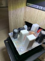
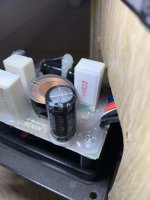
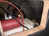
A big challenge was to mount the finished PCB inside the cabinets. All looks good. Sound is fantastic.
In the meantime, I've upgraded Zensor 7.
Since the elements are quite large, I made a new board from scratch. I used 1.6 mm board.
Componets:
- Capasitors- Jantzen Audio Superior Z-cap
- Resistors - Mundorf Supreme
- Inducrors - Jantzen Wax Coil
- Mundorf 9.5% silver gold solder supreme
A big challenge was to mount the finished PCB inside the cabinets. All looks good. Sound is fantastic.
Attachments

They act in such a way because they're...🤔 ,not as cool as Brits (B&W) are.
And then there is this fact that there is no warranty at all, except for ridicilous flaws.
And then there is this fact that there is no warranty at all, except for ridicilous flaws.
gaszto... is the any chance you could remove L1 and L2 from the PCB and read values?Hi,
I attached the schematic of the Oberon 7 Crossover
I don't have precise LCR meter to measure inductance but L1 somewhere 0.6-0.8mH the other parts are there. I have replaced R1 to Mundorf M Resist Ultra, R2, C1 Jantzen Standard Z-cap, C2 4,7uF Superior Zcap+.2.2uF Silver Zcap mix.
View attachment 1127876
They are underneath, printed on PCB. I will be grateful for such help.
- Home
- Loudspeakers
- Multi-Way
- Dali Oberon 7 - crossover wiring diagram (schematic)