Did some measurements of fault pins. FAULT goes low and CLIP stays high. OC_ADJ resistor is 22k so CB3C. Seems some kind of overcurrent protection.. I need to toggle RESET to make it work again. Once I managed to only shut down one channel. Speakers are 4 ohm and working okay on other amps, eg tpa3116.Hi,
I have the 4 channel board and am trying to figure out the problem of why I can't run both channels on one chip. If I connect one channel of each chip to speakers it is working good, 200w no problem. When I connect two speakers to only one chip, it comes to less than 10w and then shuts off. I am figuring out how can I acces the clip an fault pins but currently dont have a small soldering iron. Any idea why this happens? Thanks! View attachment 1119009
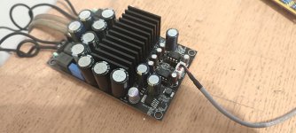
how about you heatsink?Did some measurements of fault pins. FAULT goes low and CLIP stays high. OC_ADJ resistor is 22k so CB3C. Seems some kind of overcurrent protection.. I need to toggle RESET to make it work again. Once I managed to only shut down one channel. Speakers are 4 ohm and working okay on other amps, eg tpa3116.
It makes good contact with the chip, also changed thermal paste.how about you heatsink?
🤔 Obviously, all these cards cannot produce the announced power...
I have often noticed, me too, the loss of a channel, after having pushed the volume ...
I did not have this problem with the 3e audio board ...
Non-compliant TPA ...which should have been scrapped or bad designed from the card?
Now... i try Ma5332! ....It's a tpa killer !
I have often noticed, me too, the loss of a channel, after having pushed the volume ...
I did not have this problem with the 3e audio board ...
Non-compliant TPA ...which should have been scrapped or bad designed from the card?
Now... i try Ma5332! ....It's a tpa killer !
Last edited:
Which board exactly?Now... i try Ma5332! ....It's a tpa killer !
I think only three ready made exist. The very expensive eval board. One without PSU and one with integrated PSU
hi all. I also purchased an improved amplifier board on tpa3255, at first I wanted all the electrolytes, but for now I left it as it is. There was a thermal pad under the radiator, I replaced it with thermal paste. now I assembled a DIY amplifier on this board, here is an example -
after I measured the damping coefficient, it turned out to be very low, about 20. any suggestions about this?
hi all. I also purchased an improved amplifier board on tpa3255, at first I wanted all the electrolytes......
Good day Alex.
I've been playing around with this amplifier board too. Esr wise, all the factory installed capacitors measure very well - a little better than the Panasonic fc's /elna caps I bought to replace them. The exception are the 10uf 16v gold caps that measure at 2.52 on average. The three x 1000uf 50v parallel caps (according to the pcb) are worthy of your attention however. These caps (2x1000uf and 1x560uf - as installed at factory) actually measure up as 2x770uf and 1x420uf (about 1960uf in total) total). As I bought two of these boards so it was easy to compare between the 2. I found that by replacing the middle 560uf/50v cap with the same 1000uf donated from the second board there was a substantial sound improvement, without any further changes. Everything sounds more cohesive and the improvements in sound separation can't be overstated. Highly recommend anyone playing with this board replace that skinny 50v cap as a proper baseline before commencing any further changes.
Thank you very much, this is valuable information, I will try. Yes, one more thing I noticed, when powered by a 42 volt unit, the amplifier heats up more than from 24 volts, just observations.Good day Alex.
I've been playing around with this amplifier board too. Esr wise, all the factory installed capacitors measure very well - a little better than the Panasonic fc's /elna caps I bought to replace them. The exception are the 10uf 16v gold caps that measure at 2.52 on average. The three x 1000uf 50v parallel caps (according to the pcb) are worthy of your attention however. These caps (2x1000uf and 1x560uf - as installed at factory) actually measure up as 2x770uf and 1x420uf (about 1960uf in total) total). As I bought two of these boards so it was easy to compare between the 2. I found that by replacing the middle 560uf/50v cap with the same 1000uf donated from the second board there was a substantial sound improvement, without any further changes. Everything sounds more cohesive and the improvements in sound separation can't be overstated. Highly recommend anyone playing with this board replace that skinny 50v cap as a proper baseline before commencing any further changes.
Проверил на своей плате, конденсаторы на 50 вольт изначально стоили 2 на 1000мф и один на 470мфДобрый день Алекс.
Я тоже игрался с этой платой усилителя. Что касается Esr, то все установленные на заводе конденсаторы измеряют очень хорошо — немного лучше, чем конденсаторы Panasonic fc/elna, которые я купил для их замены. Исключением являются золотые колпачки 10 мкФ 16 В, средний вес которых составляет 2,52. Однако три параллельных конденсатора по 1000 мкФ 50 В (согласно плате) заслуживают вашего внимания. Эти конденсаторы (2x1000 мкФ и 1x560 мкФ - установленные на заводе) на самом деле составляют 2x770 мкФ и 1x420 мкФ (всего около 1960 мкФ). Поскольку я купил две такие платы, их было легко сравнить между собой. Я обнаружил, что при замене средней крышки 560 мкФ/50 В на те же 1000 мкФ, пожертвованные второй платой, звук значительно улучшился без каких-либо дальнейших изменений. Все звучит более связно, а улучшения в разделении звука невозможно переоценить.
TRANSLATION: I checked it on my board, 50 volt capacitors initially cost 2 for 1000mf and one for 470mf
 Please post in English.
I bought a used 3e audio 3255 asssemly, someone else built following the ieee article
https://spectrum.ieee.org/build-your-own-professionalgrade-audio-amp-on-the-sort-of-cheap.
BTW I would love to have a copy of the full article if anyone has the pdf to share.
I'm comfortable soldering and/or molex connecting my way, but no PCB design, not an EE.
I have my AMP with input from laptop, 1/8" jack split to RCA. Output to a pair of Bagend MM8 monitors and Bagend Powered Sub.
Playing with VLC, volume set to apx 40% and it faults, with one channel cutting out.
The entire unit is out in my barn, so at this time of year it's cold and the fault occurs with any volume applied.
Leaving at 40% as soon as a passage bumps output it faults.
I have no idea where to start, but I'd like to fix this or else I'll have to start over.
You may well be right actually. My mistake.Проверил на своей плате, конденсаторы на 50 вольт изначально стоили 2 на 1000мф и один на 470мф
but I will try to change them for others of 1000mfYou may well be right actually. My mistake.
I changed all of electrolitics capacitors...but I will try to change them for others of 1000mf
Attachments
what was the result?I changed all of electrolitics capacitors...
- Home
- Amplifiers
- Class D
- TPA3255 - all about DIY, Discussion, Design etc