Don't worry. It's only 12V going to opamps.Oh crap. Are the opamps on the same voltage as the rest of the board? I run mine at 51V which means the OPA1656 I just ordered are not going to work then...
What does this achieve?I like both the OPA1656 and OPA1612, they sound even better in my opinion if you put a 0.1uF poly cap across the power and ground pins (4 and 8 in the case of a dual opamp).
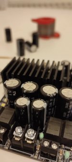
I started the modification of "improved" chinese board... I soldered 4 pieces of 2200 uF 25V, and 3 pieces of 1000 uF/50 capacitors from NIC Components NRWS series. I'm still waiting few ELNA Silmic II for input, and Panasonic FC's for power supply
Attachments

they're not. MLCCs they are.yes correct those are tantalums.
Are they polarised? if not they could be mylaryes correct those are tantalums.
no, it is a part of output LC filter, n thus non-polarAre they polarised? if not they could be mylar
Hello 3E Audio. Is it the final price?the board finally come out and looks good, i am planning to build heatsink panel and it take another few weeks.
if someone don't need heatsink then you can take it now.
@daniboun you may interesting on this version as you own lots of experience on TPA32xx and other high-end stuff.
https://www.aliexpress.com/item/100...b16700654973546242ed87e!12000030475078708!rec
A little more expensive than promised... Maybe available product without inductors and opamps at a cheaper price?
This board has issue with heat dissapation, it using a low quality thermal pad between the chip and heatsink. The heat could not transfer quickly to heatsink so get OTE.I started the modification of "improved" chinese board... I soldered 4 pieces of 2200 uF 25V, and 3 pieces of 1000 uF/50 capacitors from NIC Components NRWS series. I'm still waiting few ELNA Silmic II for input, and Panasonic FC's for power supply
Second is it run at 450khz pulse, i would change it to 600khz
I have a relatively sensitive speakers (Canton CT-1000 3. gen), I don't want too much power.This board has issue with heat dissapation, it using a low quality thermal pad between the chip and heatsink. The heat could not transfer quickly to heatsink so get OTE.
Second is it run at 450khz pulse, i would change it to 600khz
"Second is it run at 450khz pulse, i would change it to 600khz"
For this only need change the freq adj. resistor to 10 kohm? Nothing else? Thanks for help!
Yes, i had just only changed R freq from 30.9k to 10k, the pwm increased to 600khz, the RMS vol at no signal also reduced about 500mV, before it above 1V"Second is it run at 450khz pulse, i would change it to 600khz"
For this only need change the freq adj. resistor to 10 kohm? Nothing else? Thanks for help!

Thanks! And what happened the "switching off" problem, what you described early?Yes, i had just only changed R freq from 30.9k to 10k, the pwm increased to 600khz, the RMS vol at no signal also reduced about 500mV, before it above 1VView attachment 1116490
That is when i connect R channel to load then turn up my DAC (even with music not test tone) to about 12 o’clock, L channel also get but more at almost maximum. The FAULT lamp off, the CLIP lamp does not any blink, board is muted and the board is wait RESET to back normal.Thanks! And what happened the "switching off" problem, what you described early?
I removed the thermal pad and take direct the heatsink to chip suface, now the board could handle better, still shutdown but more louder than before in both 2 channels
Last edited:

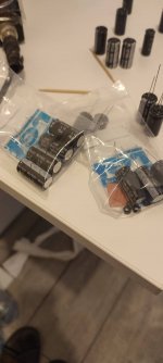
I replaced all the parts I had thought of. View attachment 1117297
What's the result?
I have Opamps on the way for my 3e boards, but am thinking about adding bypass caps for the new opamps, and perhaps bypass camps on the power inputs as well...
I have been listening for about 15 minutes, and quietly, the family is resting...What's the result?
I have Opamps on the way for my 3e boards, but am thinking about adding bypass caps for the new opamps, and perhaps bypass camps on the power inputs as well...
You've really hit the gate running. Quite curious about the components you've removed - do you plan to measure their actual capacity/esr by any chance? It could be interesting to know whether replacing certain caps is an option or a necessity. Also, is it right that you're using silmic caps for the audio input? I experimented with them on the earlier shui yuan and found the results quite disappointing.I have been listening for about 15 minutes, and quietly, the family is resting...
Kind regards
I listened few hours, and I think the mod. worth the approxx 15 USD cost and the 1-2 hours work. For my ears the sound is more natural, and the bass goes deeper and the resolution is higher, but no range is overemphasised. IMHO the no fake capacitors (from trusted seller) are more reliable than potentially fake capacitors.
The built-in components: Panasonic FC 820uf/25V x 2, NIC Components 2200 uF/25V x 4, Elna Silmic II 10uF/35V x 6, Panasonic OsCon 560uF/16V, Panasonic FC 1000 uF/16V x 3, JRC4580 x2
The built-in components: Panasonic FC 820uf/25V x 2, NIC Components 2200 uF/25V x 4, Elna Silmic II 10uF/35V x 6, Panasonic OsCon 560uF/16V, Panasonic FC 1000 uF/16V x 3, JRC4580 x2
Last edited:
it is hard to compare the sound of anything when they are played a few seconds apart. Doing it after doing the mods, provablyy 30 mins or more later make a the comparison very subjective.
Hi,
I have the 4 channel board and am trying to figure out the problem of why I can't run both channels on one chip. If I connect one channel of each chip to speakers it is working good, 200w no problem. When I connect two speakers to only one chip, it comes to less than 10w and then shuts off. I am figuring out how can I acces the clip an fault pins but currently dont have a small soldering iron. Any idea why this happens? Thanks!

I have the 4 channel board and am trying to figure out the problem of why I can't run both channels on one chip. If I connect one channel of each chip to speakers it is working good, 200w no problem. When I connect two speakers to only one chip, it comes to less than 10w and then shuts off. I am figuring out how can I acces the clip an fault pins but currently dont have a small soldering iron. Any idea why this happens? Thanks!
- Home
- Amplifiers
- Class D
- TPA3255 - all about DIY, Discussion, Design etc