My entire system, except for my modern AVR is vacuum tube. Most of it is kit based, modern and vintage.
I really wanted a solid state amplifier for when I wanted a lot of power. I came across a Hafler DH-200 on eBay. Appears to be kit built and largely untouched since being build.
I replaced the bad power switch, broken fuse holder, all the capacitors on the driver boards and inspected the rest of the solder joints, finding a few bad ones.
Set the Bias at 275 mA. The 200 does NOT have a DC offset adjustment.
Well, I measured the DC offset on the left channel I have -66 mV and on the right channel I have -331 mV
I have been told that to correct this I need to replace the Q1, Q2, Q5, and Q6 transistors and they need to be gain matched. I can purchase new transistors from NTE but I cannot seem to find a matched pair.
Manual shows these as
Q1/Q2: 2N5550
Q5/Q6: 2N5401
I am well aware that there is more than one person selling replacement boards for these units. Redesigned, and “upgraded” but I like to listen to things as they were designed. I would really like to fix the DC offset on this Amplifier using the original configuration.
Does anybody have any insight as to where I can find matched pairs of these transistors? Or if my diagnosis is incorrect, what should I be looking at?
Thank you so much for your help
Last edited:
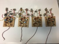
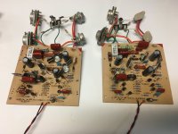
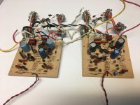
I have four input boards, two original I cut out of a working amp years ago, two that had new caps and transistors installed after a failure. You can see the burn marks under a couple of resistors on the PCB.
If your interested PM me.
If your interested PM me.
Attachments
If you find these transistors you might also consider cascoding the input stage per Richard Marsh. You'd need to double up on the transistors.
Let us know if you find a source.
Let us know if you find a source.
Is there a spec somewhere for offset error at the amp output?
There's some chance that output offset is worsened by leakage through C5. IMO, it would be good to look for leakage before pursuing replacement of input differential transistors. If you want to explore this notion, please make 4 voltage measurements on each channel:
+ input (i.e. junction R4,R5)
- input (i.e. junction R20,R21)
output (i.e. junction R22,R23)
- ratio (i.e. junction R23,R25)
Make all measurements re junction R25,R39 (i.e. board terminal 2), with 1mV resolution or better if possible. Be sure to report negative voltages with a minus sign.
This might reveal cap leakage, but no guarantees.
I have replaced all the capacitors on the boards with new ones. The DC offset was the same prior to replacing the caps. The offset is to be “as close to 0 as possible”Is there a spec somewhere for offset error at the amp output?
There's some chance that output offset is worsened by leakage through C5. IMO, it would be good to look for leakage before pursuing replacement of input differential transistors. If you want to explore this notion, please make 4 voltage measurements on each channel:
+ input (i.e. junction R4,R5)
- input (i.e. junction R20,R21)
output (i.e. junction R22,R23)
- ratio (i.e. junction R23,R25)
Make all measurements re junction R25,R39 (i.e. board terminal 2), with 1mV resolution or better if possible. Be sure to report negative voltages with a minus sign.
This might reveal cap leakage, but no guarantees.
From what I have heard, under 50mv but up to 100 is “ok”
I ordered 20 transistors (they are $0.12/each) and I’m going to hand match them. Seems to be the best way to get them. Thank you though. If I fry these I’ll take you up on those boards you have!I have four input boards, two original I cut out of a working amp years ago, two that had new caps and transistors installed after a failure. You can see the burn marks under a couple of resistors on the PCB.
If your interested PM me.
Simply add DC servo on OPA192 OpAmp [for example - https://www.patreon.com/posts/64958853 ] and you will get less than 20 microvolts offset without any adjustment or matching.
- Home
- Amplifiers
- Solid State
- Hafler DH-200 DC Offset