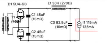
This is the schematic for the 1000V, sorry I did not want to bore everyone with the detail - I was just pondering the calculation for the Balancing resistors 🙂Tonescout, you are being a bit minimal on technical detail and scope. It seems that you are making a 1kV power supply without any schematic, detailed design, or specific part identification (eg. the link to metallized poly caps just says 200-500Vac voltage rating), which makes for a feeling of unease in providing any advise.
Caps are 800V DC Shizuki WME metalized PP oil filled. to get the 82.5 I have 3 pairs of 45uF and one pair of 15uF which is all I can fit in the chassis.
The layout will include balancing resistors across each cap at probably about 4M (Allen Bradley 2W).
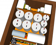
The layout for the whole PS is contained within an oak chassis, the sketch is viewed from the top of the amplifier with the transformers and top plates missing in the view.
Current set up viewed below: I will put an insulation sheet/cover on the top of the capacitors that will sit near (10mm away) from the aluminium plate that holds the top mounted output TRFs.
The bank of caps will sit on a copper plate that is mounted as a pre-assembled module to the chassis.
Chokes all in situ using the old electrolytic caps (4 in series here at 400V)
I have not shown the driver PS design here, this is 500V from the half up supply.
Attachments
Thanks, I had help in the original build 25 years ago!Looks very well laid out, nice build.
This is my forever power amp, with efficient speakers - just slowly improving it
Can you elaborate (or show a schematic) of how you connected those caps? Can you link to a spec/datasheet for the capacitor?Caps are 800V DC Shizuki WME metalized PP oil filled. to get the 82.5 I have 3 pairs of 45uF and one pair of 15uF which is all I can fit in the chassis.
The capacitors are all Shizuki/ASC 450v AC. https://ascapacitor.presencehost.net/file_download/45034a98-ddb7-435c-92f7-2b50d3cb2241Can you elaborate (or show a schematic) of how you connected those caps? Can you link to a spec/datasheet for the capacitor?
and quoted to be good for 800V DC
Here is the schematic of the PS and the circuit 6C45 driver valve and 211 power valve.
Just my 2c worth, but my concerns would be:
- have you measured the PT secondary voltages at your nominal mains ACV, and have you measured if your mains AC varies much?
- the capacitor datasheet doesn't show or indicate a DCV rating, and doesn't indicate a VAC tolerance, which may infer that 640Vdc is a possible max rating.
- The datasheet also indicates there are two protectives devices in series with the internal cap, so it would be in your interests to do an ESR measurement, as your PSUD2 schematic shows a very low ESR.
- Are you using the 2W Bradley from post #14, as it only has a peak 500Vdc rating. Were you just going to use one 4M7 resistor across each cap?
- the 4M7 has a very long time-constant for bleed discharge if ever a choke or other load is not connected (eg. by accident). That is quite a risk, and that risk would be compounded if the 4M7 was not soldered direct to the cap spade lugs (eg. mounted elsewhere and connected by spade lugs).
- one can only presume the cap tolerance rating is +/-10%, so it would be in your interests to measure and pair the caps for actual capacitance, to minimise imbalance.
- it is not uncommon for a 5U4 to arc over, so I'd strongly recommend you insert 3x series 1N4007 in series with each 5U4.
- I'd recommend inserting a 250Vac fuse in the PT 450Vac winding, for accidental over-current protection.
- I'd recommend an overvoltage protective device across the output stage primary winding, as that point is under the highest voltage stress in the system.

AC incoming it does vary but goes down to 230V and not up by much max is 244V - I have not measured variation in PT secondary but once at 493VJust my 2c worth, but my concerns would be:
- have you measured the PT secondary voltages at your nominal mains ACV, and have you measured if your mains AC varies much?
There are a number of resellers quoting this value. e.g. http://www.acoustic-dimension.com/
- the capacitor datasheet doesn't show or indicate a DCV rating, and doesn't indicate a VAC tolerance, which may infer that 640Vdc is a possible max rating.
I have done this. They all measure 20 or 30 mOhm on a cheap ESR meter, the figures came from the manufacturer.
- The datasheet also indicates there are two protectives devices in series with the internal cap, so it would be in your interests to do an ESR measurement, as your PSUD2 schematic shows a very low ESR.
These are quoted here for HB 2W at 750V
- Are you using the 2W Bradley from post #14, as it only has a peak 500Vdc rating. Were you just going to use one 4M7 resistor across each
Yeah across each cap
- cap?
Will be soldered directly
- the 4M7 has a very long time-constant for bleed discharge if ever a choke or other load is not connected (eg. by accident). That is quite a risk, and that risk would be compounded if the 4M7 was not soldered direct to the cap spade lugs (eg. mounted elsewhere and connected by spade lugs).
They measure very close, see image attached, I measured twice as you can see.
- one can only presume the cap tolerance rating is +/-10%, so it would be in your interests to measure and pair the caps for actual capacitance, to minimise imbalance.
They have Ohmite Brown 100R across the contact terminals to help manage this I think?
- it is not uncommon for a 5U4 to arc over, so I'd strongly recommend you insert 3x series 1N4007 in series with each 5U4.
OK, thanks
- I'd recommend inserting a 250Vac fuse in the PT 450Vac winding, for accidental over-current protection.
OK, thanks
- I'd recommend an overvoltage protective device across the output stage primary winding, as that point is under the highest voltage stress in the system.
THANKS for all the guidance 🙂
Ta. So the HB 2W are HB series for 750Vpk rating. Also worth matching those values to better than 5% if you can, to minimise the static voltage unbalance.
I'm not sure what you mean by Ohmite brown 100R - perhaps a series resistance to manage the peak current levels. But that is not what I was suggesting - which relates to avoiding PIV breakdown in the 5U4 - the most common reference to that aspect is the 'yellow sheet mod' - a link to the design aspect is below (in section 7.4 and 2.1):
https://dalmura.com.au/static/Power supply issues for tube amps.pdf
Do you use PSUD2 much to design a PS circuit?Ta. So the HB 2W are HB series for 750Vpk rating. Also worth matching those values to better than 5% if you can, to minimise the static voltage unbalance.
I'm not sure what you mean by Ohmite brown 100R - perhaps a series resistance to manage the peak current levels. But that is not what I was suggesting - which relates to avoiding PIV breakdown in the 5U4 - the most common reference to that aspect is the 'yellow sheet mod' - a link to the design aspect is below (in section 7.4 and 2.1):
https://dalmura.com.au/static/Power supply issues for tube amps.pdf
I do, as it is a simple way to provide some confidence in what to expect. It does need some supporting measurements of transformer and choke part parameters to mitigate uncertainty in results.Do you use PSUD2 much to design a PS circuit?
- Home
- Amplifiers
- Tubes / Valves
- Calculating balancing resistors