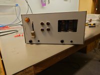
Hello,
Just got my first amp with OTs going after some troubleshooting. First tried it with my crappy testing phones and it seemed alright, about as tinny as I'd expect from 1¢ phones from a 1¢ source, so I tried my HD558s with my phone as the input and it's still just as bad.
Sounds like a high-pass filter basically, no bass what so ever compared to plugging the phones into my phone.
There are no coupling caps so all I have left to suspect are dumb mistakes, the core design, the tubes(?) and the OTs.
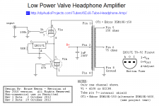
This is the schematic I based my build on:
http://diyaudioprojects.com/Tubes/6DJ8-Tube-Headphone-Amp/
I did not use the transformer or PSU specified because I had some small OTs I have characterised and found fairly suitable in the lab, with 0dB @1kHz the -3dB span was about 100Hz-40kHz if the levels were in the 100mV range on the secondary.
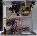
As for the PSU, I wound my own power transformer, used a bridge rectifier and then 440uF + small poly cap for the reservoir and a 1.7kOhm resistor into another 440uF + small poly cap for the B+. (what's the deal with tube PSUs always using caps <=100uF, we're not in 1950 anymore)
The heaters are AC for longevity, +-3.15V around ground.
The ECC88s i have installed seem like new production ones, they don't look particularly well made honestly but they seem to function alright. I don't have any known NOS ones but I do have more ECC88s in my collection I could swap in.
I also started looking at the specs of the tube and the load line and well, the schematic as drawn and what I've built both exceed power and voltage limits, especially as designed with 32 ohm headphones it seems all sorts of bad.
Tl:dr:
Built basically this amp:
http://diyaudioprojects.com/Tubes/6DJ8-Tube-Headphone-Amp/
But with a different OT and PSU, there is no bass when playing music. Sounds like I've made a high-pass filter but there are no coupling caps in the signal path. Any ideas what to suspect?
Just got my first amp with OTs going after some troubleshooting. First tried it with my crappy testing phones and it seemed alright, about as tinny as I'd expect from 1¢ phones from a 1¢ source, so I tried my HD558s with my phone as the input and it's still just as bad.
Sounds like a high-pass filter basically, no bass what so ever compared to plugging the phones into my phone.
There are no coupling caps so all I have left to suspect are dumb mistakes, the core design, the tubes(?) and the OTs.
This is the schematic I based my build on:
http://diyaudioprojects.com/Tubes/6DJ8-Tube-Headphone-Amp/
I did not use the transformer or PSU specified because I had some small OTs I have characterised and found fairly suitable in the lab, with 0dB @1kHz the -3dB span was about 100Hz-40kHz if the levels were in the 100mV range on the secondary.
As for the PSU, I wound my own power transformer, used a bridge rectifier and then 440uF + small poly cap for the reservoir and a 1.7kOhm resistor into another 440uF + small poly cap for the B+. (what's the deal with tube PSUs always using caps <=100uF, we're not in 1950 anymore)
The heaters are AC for longevity, +-3.15V around ground.
The ECC88s i have installed seem like new production ones, they don't look particularly well made honestly but they seem to function alright. I don't have any known NOS ones but I do have more ECC88s in my collection I could swap in.
I also started looking at the specs of the tube and the load line and well, the schematic as drawn and what I've built both exceed power and voltage limits, especially as designed with 32 ohm headphones it seems all sorts of bad.
Tl:dr:
Built basically this amp:
http://diyaudioprojects.com/Tubes/6DJ8-Tube-Headphone-Amp/
But with a different OT and PSU, there is no bass when playing music. Sounds like I've made a high-pass filter but there are no coupling caps in the signal path. Any ideas what to suspect?
Attachments
It would be better with a schematic. Bass needs more energy to drive speakers, so perhaps the current in the output stage is insufficient providing you said no caps in the direct audio path.
For headphones? How much current does the output stage need to sink into 50 ohm headphones to make 1mW or so at 40Hz? The headphones' sensitivity is probably around 100dB SPL with 1mW input, but that would be at 1kHz, not 40Hz.Bass needs more energy to drive speakers, so perhaps the current in the output stage is insufficient...
The Sennheiser HD558 has impedance of 50 ohms, which is a heavy load for a tube amp. What Osvaldo asked could very well be the best question. Does the amp circuit drive that heavy load sufficiently well?as tinny as I'd expect from 1¢ phones from a 1¢ source, so I tried my HD558s with my phone as the input and it's still just as bad.
Also, the bass response of an amp using an output transformer (OPT) is dependent on the primary inductance of that OPT. We don't know what transformers you used. If the primary inductance (Lpri) is very low, those OPTs will not pass much bass no matter what size capacitors you use in the PSU.
Also,
-3dB at 100Hz? That might sound tinny right there. I'd prefer to see -3dB at 50Hz from the OPT, at worst. These OPTs may not be up to the task.I did not use the transformer or PSU specified because I had some small OTs I have characterised and found fairly suitable in the lab, with 0dB @1kHz the -3dB span was about 100Hz-40kHz if the levels were in the 100mV range on the secondary.
Last edited:

Sennheiser HD558 is a bad choice for your output transformer. The impedence peaks at 270 ohms at 100 Hz, and it is anything but flat at low frequencies. The high impedance at 100 Hz means the HD558 gets less power per volt at that frequency. I also have a headphone with the same issue. To get a better frequency response, I use a standard 5k over 8 ohms transformer, and a resistive attenuator at the output. This way, the output tube load is more constant over the full audio range because the headphone impedance is connected in parallel with a low value resistor.
Neither do I 🙂 absolutely no clue, they have no markings or anything .We don't know what transformers you used.
They are salvaged from a to me unknown piece of audio gear, I just know what I've tested. The numbers I mentioned was with it set up with the expected loads in this amp.
They theoretically only present about the same load to the tubes as 32 ohm phones would through the 75 ohm tap of the original ones, but according to the author, that should be just fine besides maybe having to turn the volume up some.
I can use an LCR meter to find the inductance of the primary/secondary but I won't have it for a few days. I belive its somewhere around 1000mH on the primary. Could be half that, I have never measured them.
Tried it with my WH1000XM3s for something with a lot more bass, and they have the same issue.Sennheiser HD558 is a bad choice for your output transformer. The impedence peaks at 270 ohms at 100 Hz, and it is anything but flat at low frequencies. The high impedance at 100 Hz means the HD558 gets less power per volt at that frequency. I also have a headphone with the same issue. To get a better frequency response, I use a standard 5k over 8 ohms transformer, and a resistive attenuator at the output. This way, the output tube load is more constant over the full audio range because the headphone impedance is connected in parallel with a low value resistor.
Less so, but it's not just the impedance curve at play here as a lot of the lower end is still just absolutely gone. Don't own anything higher impedance, but I do own some 8 ohm headphones and they are about the same, just not as loud.
Good point with the resistor network though, I'll build a little box for that once I'm back in the lab, or maybe a couple of them for different impedance matches even 🙂
Schematic attached to this post 🙂It would be better with a schematic. Bass needs more energy to drive speakers, so perhaps the current in the output stage is insufficient providing you said no caps in the direct audio path.
As for the power, its described as being 50mW into the headphones which would be enough to blow my eardrums with the headphones I use so I belive the power should be there. Looking at similar OTs to the one I have they are rated for about 500mW so I belive there should be plenty of headroom in the OTs. But the issue is there at any level, it dosnt get more even between the highs and lows at lower volume.
Attachments
Also measured the heater voltage and its a bit low, only about 5Vrms, could that be the culprit?
Heaters look to be glowing alright but maybe they aren't hot enough. No clue as I've not used these tubes before but they glow about the same as the double triode in my other builds
Heaters look to be glowing alright but maybe they aren't hot enough. No clue as I've not used these tubes before but they glow about the same as the double triode in my other builds
5V on a nominal 6.3V heater is almost 20% below normal. That will result in reduced transconductance from the tube (it won't be lit up as hot), which will result in higher internal plate resistance, which will interact with the far too low inductance of your OPT's primary to make the bass response even more deficient.
From what I can see,
1. The OPT primary inductance is far too low. For a 6DJ8 you want the primary inductance to be at least 30H. Is your OPT's primary inductance really only 1H? That's way too low.
2. The rp of a 6DJ8 at these operating points is probably no lower than 2.5k ohms. You might want to try a different twin-triode with lower rp, such as 6N6P or 5687. The downside is that they have lower mu (less gain) than 6DJ8 (aka ECC88, 6922, E88CC) and require double (or more) the heater current (800mA for 6N6P vs 300mA for 6DJ8 or 365mA for 6922/E88CC).
3. The heater needs to be the right voltage, and with enough current capacity, or the operating characteristics of the tube you use will be degraded (gm goes down, rp goes up).
No clue, it's a guess based of the datasheet for an unrelated transformer I found that looks similar but dosnt seem to come in this ratio or winding. Never measured, but I highly doubt its 30H. All I know is that it seemed not good but maybe alright when testing it on the bench with loadings matching this application.1. The OPT primary inductance is far too low. For a 6DJ8 you want the primary inductance to be at least 30H. Is your OPT's primary inductance really only 1H? That's way too low.
Will look into the heater issue, I'll probably not bother rewinding it and I'll just slap in another transformer, I've got a load of them that go to 6V. Might help with some mechanical damping as well I suppose.
Don't have any 6N6P around but I might have a 5687 or two, don't remember, my collection is a mess. I'd prefer to stick to the ECC88 though as I have quite a few.
Something might be wrong with the LM 317. Push pull operation of the ECC 88 is dependent on that ic. ; if it's broken you don't have pp operation but single ended from only one tube-half. As your PP OT cannot stand the dc current of the tube, the primary induction becomes very low hence practically no low frequency output remains.
That's an interesting point, I'll check if its drawing the appropriate amount of B+ current once I get some time in the lab. Last time I checked it seemed to be the 50mA expected(well, 47mA is what I calculated based off voltage drop across the PSU resistor I measured), but that was also measured when the B+ was incorrectly 167V.Something might be wrong with the LM 317. Push pull operation of the ECC 88 is dependent on that ic. ; if it's broken you don't have pp operation but single ended from only one tube-half. As your PP OT cannot stand the dc current of the tube, the primary induction becomes very low hence practically no low frequency output remains.
Right now it's 150V but that's a solid 20V over what the datasheet would say is max, but 7V under what the PSU in the schematic seems to be outputting... Very confusing, but I think I'll be reducing it to 130V over the tubes instead of 150V unless someone says otherwise.
The problem might also be the OT. A long time ago someone came to me with a similar problem. No bass. It appeared that he had one anode connected correctly and the other one with the midpoint of the primary while the end of the primary (destined for the second anode) had been connected with 250 v. Of course music came out of it and it sounded a bit strange but he thought this was the character of the amp!
It sometimes happens that connections on transformers appear illogical and maybe that's the case here.
The only other possibility is that something is wrong with the OT itself.
If the anode currents of the ECC 88 halves are equal and the OT is all right this thing has to produce bass, no doubt about it.
Loads, but did you approximate the source? A cheap transformer may do OK with 50 ohm source, but a pair of triodes is maybe 10k source. 1000mH 1H from 10k is 1,600Hz low-cut, which sure would be "no bass".salvaged from a to me unknown piece of audio gear, .... The numbers I mentioned was with it set up with the expected loads in this amp.
..... . I belive its somewhere around 1000mH on the primary.
Can you get a 240VCT to 24V(CT) 50/60Hz power transformer? 40VA 24V transformers are often used with heating thermostats and sell for $25.
https://www.amazon.com/Control-Transformer-Primary-Secondary-Furnace/dp/B07RDBS6NK
The 240V side will (probably) be over 10k down to below 100Hz. If that is a lot better, then your "unknown" irons are just wrong.
Yup. Set up as expected from this amp on primary and secondary.but did you approximate the source
The mH is literally a guess, it could be anything. Maybe it's 1H, maybe 500H, maybe 0.1H no clue. As with any surperfolus information I mention on this forum, I regret even naming a number instead of just saying that I haven't measured.
I have some 220V to 24V ones, but I belive they would be quite a bit worse for this application from what I remember from my testing some months ago. Could retry them, it's been a bit so I don't remember quite why I discarded them for this application.
Also the low cut I belive is in the sub 200Hz at least. Definitely bellow 300Hz, not the 1600Hz you mention 🙂
Best if you put some effort measuring the value. It probably is not so simple if you have no access to an LCR meter, but a small 6-12v transformers, a 10k potentiometer and a few resistors will allow you to measure using a multitester. Find R where VR = VL then L=R/2Πf where f is your mains frequency.The mH is literally a guess, ...
As Lord Kelvin said it :
I often say that when you can measure what you are speaking about, and express it in numbers, you know something about it; but when you cannot measure it, when you cannot express it in numbers, your knowledge is of a meagre and unsatisfactory kind; it may be the beginning of knowledge, but you have scarcely, in your thoughts, advanced to the stage of science, whatever the matter may be.
I do have an LCR meter 🙂Best if you put some effort measuring the value. It probably is not so simple if you have no access to an LCR meter, but a small 6-12v transformers, a 10k potentiometer and a few resistors will allow you to measure using a multitester. Find R where VR = VL then L=R/2Πf where f is your mains frequency.
I just haven't had any time in the lab to do any measurements, been away for the holidays. Back now so should be able to measure it in the next few days hopefully
Check your wiring at input and output to ensure it’s not a phase cancellation issue.
Will definitely octupel-check because I was absolutely stumped as to why I wasn't getting any volume and it turned out that the input ground was only capacitively linked 😂...or the ground is missing off the output headphone connector.
For headphones though? Speakers would be easy to test, just swap some wires, but headphones shouldn't have this issue? It's not like the bass should go away just from inverting the signal or swapping left/rightCheck your wiring at input and output to ensure it’s not a phase cancellation issue.
- Home
- Amplifiers
- Tubes / Valves
- No bass from ECC88 PP OT headphone amp