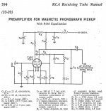
I found the below schematic from a Chinese language tube manual published in 1972 that was translated from one of the US tube manuals. I just can't figure out which tube manual. My guess is that it's most likely from RCA as 7025 was a popular tube in those famous RCA schematics, including the passive RIAA one. This one is feedback from the output tube plate to the grid, almost like a predecessor of EAR 834p. Anyone knows about this circuit? Its B+ voltage is rather low, around 150VDC. I think adding a cathode follower or FET source follower will make it more versatile.

Attachments
Not changing but if it's a stand alone phono preamp wouldn't be better to have a buffer so you can drive long cables?Why do you suppose you need to change it adding elements to a good circuit?
Certainly. Connect the grid of an cathode follower directly with the second's tube anode. a 68k cathode R and 1 mu output cap. That's all there is to it.
Not a great design. The first stage is unlinearized, and shunt feedback has a 14dB noise penalty. And you don't need the tape head feature. The EQ network has nothing defining t3 except the stage running out of gain.
Hi directdriver, love your profile picture.
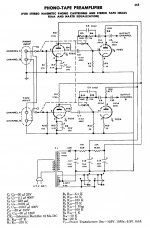
Included with this post is a working LT spice simulation of the preamp on page 636 it can be edited and experimented with as required. Also included is a picture of my computer amplifier (not home made), I also like the logo.


Included with this post is a working LT spice simulation of the preamp on page 636 it can be edited and experimented with as required. Also included is a picture of my computer amplifier (not home made), I also like the logo.
Attachments
Last edited by a moderator:
The first stage is unlinearized, and shunt feedback has a 14dB noise penalty. ....The EQ network has nothing defining t3 except the stage running out of gain.
Signal at the first stage is very small; this will not be your worst distortion. The first stage has voltage gain over 14dB, so the 2nd stage hiss will not dominate. And "all" two-triode RIAA preamps get ~~50Hz by running out of gain, or else have worse flaws.
I don't like it either. But not for these points.
I actually don't mind it so much. The first stage loading is much too steep, but easily fixed by increasing the impedances around the anode follower. Have used the same topo with battery bias for the first stage and loading issues corrected with good results. Bring the RIAA feedback from after the output coupling cap and choose an interstage coupling cap to give a 10 or 16 Hz highpass. Done.
The biggest problem with this topo is the same as the trendy no-feedback ones, the Miller C that appears as cartridge loading. Works great with low-Z high output MCs but not with classic half Henry Shures and such.
All good fortune,
Chris
The biggest problem with this topo is the same as the trendy no-feedback ones, the Miller C that appears as cartridge loading. Works great with low-Z high output MCs but not with classic half Henry Shures and such.
All good fortune,
Chris

6DJ8 would make a better input stage than 12AX7, but with roughly half the gain. That decreases THD too. The 6DJ8 would help with the input Miller C, with probably half the input C of a 12AX7.

That's cheating!
But seriously, a little more gain could be squeezed out of the anode follower with a higher Z load - you could get away with big numbers like 330K with your MOSFET buffer - and an insignificantly lower distortion.
One thing that this topo allows is a simple battery bias of the first stage. The battery sits between the input jacks' "grounds" and circuit ground. Cathodes bolted to circuit ground, 47K loads to input jacks' "ground", so the whole cartridge and its wiring and loading sits at -1.56 VDC. The drawback is that, although there's no current drawn, you have to remember to change the battery every few years. Or be like me and change the battery and battery holder every few more years. Doh!
All good fortune,
Chris
Last edited:
Hi Chris good comments re battery bias, I have used battery bias many years ago and may now have an alternative.That's cheating!
But seriously, a little more gain could be squeezed out of the anode follower with a higher Z load - you could get away with big numbers like 330K with your MOSFET buffer - and an insignificantly lower distortion.
One thing that this topo allows is a simple battery bias of the first stage. The battery sits between the input jacks' "grounds" and circuit ground. Cathodes bolted to circuit ground, 47K loads to input jacks' "ground", so the whole cartridge and its wiring and loading sits at -1.56 VDC. The drawback is that, although there's no current drawn, you have to remember to change the battery every few years. Or be like me and change the battery and battery holder every few more years. Doh!
All good fortune,
Chris
The base collector P N junction of the output transistor in a 4N27 class of optocoupler will work as as a photodiode (acting like a solar cell) and will generate a current flow that is approximately ratiometric to the LED current.
The output from the P N junction (base collector) will approximate a current source with it’s output voltage clamped to a maximum of about 580mV by the base collector junction of the photo transistor becoming forward biased by this voltage.
As the ratio from input current to output current changes with temperature and aging of the optocoupler it is best not to set the voltage by adjusting the LED input current and using a load resistor on the output. The forward biased base collector junction will set the voltage limit. I have never tested one of these out for noise it may not be possible to use it as a bias source voltage, the capacitance from the LED in the optocoupler is very low, less than a picofarad so it may even be possible to use them is series with a grid input (pending noise). The devices have quite good bandwidth in this mode so the LED should be cleanly current driven.
In my tube tester power supplies I used two optocouplers in series to give me some low current 1.2VDC galvanically isolated supplies, the tube tester uses 16 optocouplers in this mode of operation and is working flawlessly since I designed and made it.
https://sites.google.com/view/photovoltaic-operation-of-4n25/home
https://sites.google.com/view/kenstubetester
Maybe someone in this group will test this idea (battery bias replacement) before I get around to it.
Regards
Ken
You're more adventuresome than me; I'd worry about the noise on the DC supply and about the impedance of the pn junction, and about all the things I don't even know to worry about. But at least it probably won't leak and corrode stuff around it, which is a big plus.
All good fortune,
Chris
All good fortune,
Chris
Thanks for all the inputs. The reason the circuit intrigues me is that it's from a tube manual and it's different from the classic RCA passive RIAA circuit. Unlike many feedbackphobes, I don't mind having feedback in a circuit but I do like having the very first stage to be feedbackless to have a more "open" sound. Many microphone preamp circuits are designed like that. And second stage and/or buffer having feedback is completely fine with me, as buffer circuit should be as neutral and low impedance as possible. I've never listened to the EAR 834p before but its topology appeals to me. Except I prefer the first tube to have as low grid capacitance as possible for certain MM cartridges like AT or Signet. I look forward to seeing more iterations of this type. Thanks again for everyone chiming in.
@tubewerk -- just a parenthetical note -- the optocoupler is somewhat heat sensitive -- gain drift with temperature
https://www.edn.com/circuit-compensates-optocoupler-temperature-coefficient/
Scott Wurcer was able to bias the gate of a JFET using a dual gate-driver optocoupler. Neat trick. I believe the other half was used for temperature compensation.
https://www.edn.com/circuit-compensates-optocoupler-temperature-coefficient/
Scott Wurcer was able to bias the gate of a JFET using a dual gate-driver optocoupler. Neat trick. I believe the other half was used for temperature compensation.
Hi Chris The family of photovoltaic MOSFET gate drive chips are also of interest to me for use as galvanically isolated bias supply voltage sources. I have used them most satisfactorily for their intended purpose only, they are used in most solid state DC relays. The big advantage is the voltage produced is often >7VDC, dual packages are available so the outputs can be connected in series or paralleled.You're more adventuresome than me; I'd worry about the noise on the DC supply and about the impedance of the pn junction, and about all the things I don't even know to worry about. But at least it probably won't leak and corrode stuff around it, which is a big plus.
All good fortune,
Chris
https://au.rs-online.com/web/p/optocouplers/0185962
https://docs.rs-online.com/c22d/0900766b80af4d0c.pdf
https://www.infineon.com/dgdl/Infin...N.pdf?fileId=5546d462602a9dc801607b6ff8185cd0
This is the thread started by Scott to which I referred: https://www.diyaudio.com/community/...w-noise-measurement-amp-for-ikoflexer.175044/@tubewerk -- just a parenthetical note -- the optocoupler is somewhat heat sensitive -- gain drift with temperature
https://www.edn.com/circuit-compensates-optocoupler-temperature-coefficient/
Scott Wurcer was able to bias the gate of a JFET using a dual gate-driver optocoupler. Neat trick. I believe the other half was used for temperature compensation.
I am never one to discourage DIY. But if your reason for DIY is great results for low dollars, I simply don't think building the Chinese 384 clone board with some nice parts can be beat for the money. I built one with some nice tubes and quality caps, beefed up the power supply some too. The result is dead quiet black background and a nice open soundstage. Is it the best? No. But I don't think I have heard anything under $1000 solid state or tube that is better though. I used that for a long time. I ended up with an Audio Research phono pre, that I gutted, recapped and modded, which does sound better, but there's a lot more money in that box. It should sound better. If the sound matters, build the board. If it is just for fun, just go build it and tell us how it sounds and turned out~! Then we will all know. Good luck on your build....I've never listened to the EAR 834p before ...
- Home
- Amplifiers
- Tubes / Valves
- 7025 Phono Circuit From Tube Manual