Hi
Im making my first 2way speaker, i want to do as good phase as i can under other compromises.
Any feedback is appreciated, i really want to understand this..
There are "rules" like you have to change driver polarity with second order, but not really explanation why and how phase works (at least with just googling resources..) so i made this thread to see have i understood how crossover order affects phase with ideal drivers.
I have understood that for every order (1,2,3,4), highpass and lowpass moves phase out 90 degrees of original pole to different directions.
(this direction is constant as orders go higher)
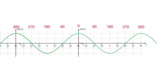
This is on flat speaker baffle:
-----------------------------------------------------------------------------------------------------------------------------------------------
-P0: First image is loudspeaker signal without crossover.
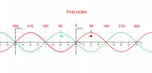
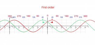
-P1: First order:
LP woofer signal has moved 90 degrees left and HP tweeter signal has moved 90 degrees right.
Both drivers are 90° out of phase looking original signal and 180° out of phase between each other.
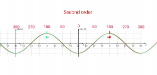
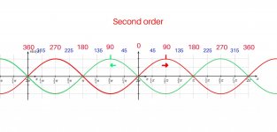
-P2: Second order:
LP woofer signal has moved 180 degrees left and HP tweeter signal has moved 180 degrees right.
Both drivers are 180° out of phase looking original signal and again in phase between each other.
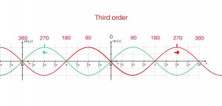
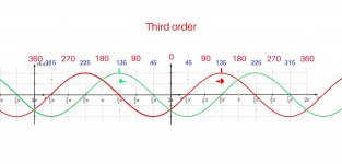
-P3: Third order:
LP woofer signal has moved 270 degrees left and HP tweeter signal has moved 270 degrees right.
Both drivers are 270° out of phase looking original signal and 180° out of phase between each other.
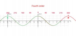
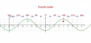
-P4: Fourth order:
LP woofer signal has moved 360 degrees left and HP tweeter signal has moved 360 degrees right. They are back in phase, but one cycle out of order.
Both drivers are 0° out of phase looking original signal and again in phase between each other.
Im making my first 2way speaker, i want to do as good phase as i can under other compromises.
Any feedback is appreciated, i really want to understand this..
There are "rules" like you have to change driver polarity with second order, but not really explanation why and how phase works (at least with just googling resources..) so i made this thread to see have i understood how crossover order affects phase with ideal drivers.
I have understood that for every order (1,2,3,4), highpass and lowpass moves phase out 90 degrees of original pole to different directions.
(this direction is constant as orders go higher)
This is on flat speaker baffle:
-----------------------------------------------------------------------------------------------------------------------------------------------
-P0: First image is loudspeaker signal without crossover.
-P1: First order:
LP woofer signal has moved 90 degrees left and HP tweeter signal has moved 90 degrees right.
Both drivers are 90° out of phase looking original signal and 180° out of phase between each other.
-P2: Second order:
LP woofer signal has moved 180 degrees left and HP tweeter signal has moved 180 degrees right.
Both drivers are 180° out of phase looking original signal and again in phase between each other.
-P3: Third order:
LP woofer signal has moved 270 degrees left and HP tweeter signal has moved 270 degrees right.
Both drivers are 270° out of phase looking original signal and 180° out of phase between each other.
-P4: Fourth order:
LP woofer signal has moved 360 degrees left and HP tweeter signal has moved 360 degrees right. They are back in phase, but one cycle out of order.
Both drivers are 0° out of phase looking original signal and again in phase between each other.
Attachments
Regarding the first order network:
At the crossover frequency, the LF driver lags 45 degrees, while the HF driver leads 45 degrees.
So the relative phase difference of the two drivers is 90 degrees.
That's just little old me giving your thread a bump so that the crossover experts will be encouraged to chime in! 😉
At the crossover frequency, the LF driver lags 45 degrees, while the HF driver leads 45 degrees.
So the relative phase difference of the two drivers is 90 degrees.
That's just little old me giving your thread a bump so that the crossover experts will be encouraged to chime in! 😉
Attachments

Im making my first 2way speaker...........so i made this thread to see have i understood how crossover order affects phase with ideal drivers.
in my book, what matters is the measured acoustic phase response.
i.e. why worry about the crossover phase or the driver phase?
Well, i would like to understand it so i can make plans or calculate in advance roughly, like how much do i have to offset tweeter behind woofer (tilted baffle angle, z-offset) for certain type of crossover. That is how i have understood it.in my book, what matters is the measured acoustic phase response.
i.e. why worry about the crossover phase or the driver phase?
(my plan is tilted baffle 2way)
Therefore i could make more correct test box from foamcore, right now my testbaffle baffle has 5° angle.
I know it works for woofer lr2/ tweeter lr4, but i would like to know how to know, or at least guess in advance..
Attachments

Your drivers are already filtered (mechanically), so when you combine that with your electrical filters you can begin to look at them like you said in your first post. (By the way, those numbers are not correct, as Galu points out. For example second order is out by 90+90)
Offsetting the drivers does not directly compensate for phase differences. It does make a change, but not necessarily the right one for simple crossover adjustment. If there is already an offset though, it can probably be managed with some careful adjustments.
Offsetting the drivers does not directly compensate for phase differences. It does make a change, but not necessarily the right one for simple crossover adjustment. If there is already an offset though, it can probably be managed with some careful adjustments.
Thanks AllenB, so i can think about it in "practical" elbow grease terms:Your drivers are already filtered (mechanically), so when you combine that with your electrical filters you can begin to look at them like you said in your first post. (By the way, those numbers are not correct, as Galu points out. For example second order is out by 90+90)
Offsetting the drivers does not directly compensate for phase differences. It does make a change, but not necessarily the right one for simple crossover adjustment. If there is already an offset though, it ca i n probably be managed with some careful adjustments.
-If i want a tilted baffle, then i will make a test cabinet with tilted baffle and Install drivers (as i have).
Measure phase/drivers with distance i want it to be in phase (my listening distance).
Put offset and tilt correctly in vituixcad (And change tilt angle/offset if needed for better phase)
and do different order crossover simulations in chosen crossover points and try to get as good phase as i can..
--------------------------------------------------------------------------------------------------------------------------------------------------
-Also, i made correction to numbers, is this right? it starts to make sense at least..
(first order is 90° phase following trough crossover, second order is back in phase with inverting driver)
Attachments
Measuring the drivers while preserving the measured distance/phase is the normal procedure. However if you were to ensure you measured from a distance from each driver which is equal to the difference at your listening position, then be careful not to double up on the distance in the simulation. For example don't go adding distance offset in VC as that will be added to what you already have.
That looks better.is this right?
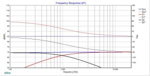
Notice the 90deg vector sum of two -3dB nets 3dB hence flat line.Regarding the first order network:
At the crossover frequency, the LF driver lags 45 degrees, while the HF driver leads 45 degrees.
So the relative phase difference of the two drivers is 90 degrees.
That's just little old me giving your thread a bump so that the crossover experts will be encouraged to chime in! 😉
different order crossover simulations in chosen crossover points and try to get as good phase as i can
when you have some results whether through sims or actual measurements, showing the phase from individual drivers, please post them.
Thanks ctrlx. I will post here link to the new thread that will be my 2way build thread.when you have some results whether through sims or actual measurements, showing the phase from individual drivers, please post them.
My midwoofer is still in post office, but after christmas it should be here so i can finally measure and start simulating..
This is very simplified description. Actually second and higher order filters can be different type of filters (Gaussian, Bessel, Chebyshev, Butterworth and so on) and they all have little different phase responses. For filter building is better to use simulation software like VituixCad and speakers measurement data with phase response.There are "rules" like you have to change driver polarity with second order, but not really explanation why and how phase works (at least with just googling resources..) so i made this thread to see have i understood how crossover order affects phase with ideal drivers.
I have understood that for every order (1,2,3,4), highpass and lowpass moves phase out 90 degrees of original pole to different directions.
(this direction is constant as orders go higher)
Last edited:
Hi, after talking about subject that is what im going to do.This is very simplified description. Actually second and higher order filters can be different type of filters (Gaussian, Bessel, Chebyshev, Butterworth and so on) and they all have little different phase responses. For filter building is better to use simulation software like VituixCad and speakers measurement data with phase response.
Im mostly interested right now in Linkwitz-Riley that should be with ideal drivers 45° + 45°: https://www.ranecommercial.com/legacy/note160.html
Do you know does the other types of filters have "stock" phase shift that should be same every time?
I could also try few of them in vituixcad and compare with LR.
In the end it kind of doesn't matter whether you aim your response like filters that have names, or you just make things up as you go along. It's OK for me to say this knowing the properties that I need fulfilled... for you I'm trying to make a point or three, whatever you pick up on. For example when you have one side done you aim to make it work with the other side regardless..... In any case it will be easier to keep your filters neat so they are easier to work with and this can be done by sticking to known curves.
I agree with you and that is what im going to do.In the end it kind of doesn't matter whether you aim your response like filters that have names, or you just make things up as you go along. It's OK for me to say this knowing the properties that I need fulfilled... for you I'm trying to make a point or three, whatever you pick up on. For example when you have one side done you aim to make it work with the other side regardless..... In any case it will be easier to keep your filters neat so they are easier to work with and this can be done by sticking to known curves.
Thing is i kind of like "academic" side of discussion and my midwoofer is still in post-office and have been for two weeks.
I called them again today and they had mislabeled it again.. I had paid two weeks ago custom and processing fee, and they had forgot to sign into the system that processing fee had been paid.. they said "tomorrow" but im not really believing anything they say at this point.
I can't start measuring, trying crossover points with active, or simulate in vituixcad because midwoofer is missing so project is on hold until it arrives.
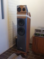
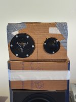
Mostly what i had done is burning in tweeters and listening which one of them i want to use in this project (pic included)
So: im kind of wasting time and trying to learn thing or two on the side..
Attachments
Far away from cut off frequency(-3 dB point) all type of filters of same order have same phase shift, difference is in region close to -3 dB point.Hi, after talking about subject that is what im going to do.
Im mostly interested right now in Linkwitz-Riley that should be with ideal drivers 45° + 45°: https://www.ranecommercial.com/legacy/note160.html
Do you know does the other types of filters have "stock" phase shift that should be same every time?
I could also try few of them in vituixcad and compare with LR.
But as told already before, you need to count also speakers acoustic phase response as actual phase is summary of filter and speaker responses. Also different distance of speakers radiation centers from measuring point will cause additional phase shift.
Last edited:
- Home
- Loudspeakers
- Multi-Way
- Have i understood phase? Images included