Interesting project Aria, just for sake of information...is there any difference if one would use 6W6 rather than 6Y6?
I gave it a try out of curiosity, but it obviously didn't work well. You have to lower the cathode resistance on the shunt circuit (begin testing with 200 ohms).Interesting project Aria, just for sake of information...is there any difference if one would use 6W6 rather than 6Y6?
Grazie mille per queste informazioni. Per questo sono un novellino! Guardando alcuni vecchi schemi per questo tubo è stato utilizzato principalmente come PP, lo schermo è stato agganciato direttamente ai rubinetti UL. Ho trovato altri schemi per SE/UL da DY'ers che utilizzavano un resistore da 40-50k, ecco dove ho avuto l'idea di farlo. Guardando di nuovo la scheda tecnica, non nomina una tensione G2 massima, quindi forse posso usare un collegamento diretto alla presa UL (proprio come faceva il vecchio Acrosound 320 amp, ma per SE? O forse sperimentare con alcuni resistori molto piccoli sotto 1k. Stavo pensando che il g2 avesse una tensione massima. Se può funzionare bene con il collegamento diretto allo schermo tocca in PP, dovrebbe andare bene così in SE giusto?
https://frank.pocnet.net/sheets/127/6/6Y6G.pdf
Il vecchio Acrosound 320 del 1955 con 6Y6 (questo è l'amplificatore che allora era ben considerato) Di maledizione, questo è dovuto principalmente all'Acrosound.
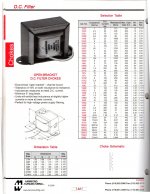
View attachment 1014414
There are some older portable amplifiers that used a SE 6Y6, but in the 135 / 135v configuration.
....also you will have about 5-6v more on the plate. If you then add this to the use of a more conventional OT than mine, which certainly has a lower DC resistance, you would still have a surplus of volts on the plate and I don't know if the 6W6 can handle them. To calibrate the shunt regulator in a less strenuous way, it would be advisable to use a 500 ohm pot to be put in series with a 150 ohm resistor on the cathode and use a tester to obtain 125v on G2. (The same is true if you are using 6Y6 and want to simplify your work).I gave it a try out of curiosity, but it obviously didn't work well. You have to lower the cathode resistance on the shunt circuit (begin testing with 200 ohms).
Last edited:
...I am reading several documents in which the use of the UL in the SE amplifier is not recommended. Why complicate your life when you already have a good sounding amp?There are some older portable amplifiers that used a SE 6Y6, but in the 135 / 135v configuration.
I've decided to change the preamp section of the project as 6AC7 tubes are quite microphonic... I'm trying to replace it with the usual CF (diagram below)... before running it full blast I'm testing the transients with a low voltage in case I made some mistake in the assembly of the components, but I can't find the prospective values... I'm looking at it again and again and it seems assembled in the right way... it is possible that, at low voltage, the presence of the diode phases the values of the transients making them all uniform?


This is the final schematics of the project... Tested, works perfectly and sounds very good... Cathode Follower preamplifier gains about 30dB and, don't forget, it's inverting... plate resistor can be any value around 80k. The 10k 7w resistor can easily be replaced by 2 x 22K 3w resistors in parallel.
The power amp delivers about 5 watts... OT can be another one with a primary between 2500 and 3500 ohms and a secondary of 8 ohms with consequent output loss of a few tens of mW .

The power amp delivers about 5 watts... OT can be another one with a primary between 2500 and 3500 ohms and a secondary of 8 ohms with consequent output loss of a few tens of mW .
Why does it need two PT's? Why CF's to drive a One M grid resister & a few picofarads?
This doesn't look definitive at all, Easily dump half the weight & expense to get the same result. 🙂
👍
This doesn't look definitive at all, Easily dump half the weight & expense to get the same result. 🙂
👍
It has two PS because it was born as two separate circuits to have the possibility of using either the preamp or the power amplifier with other circuits... anyway, are you so sure that two smaller PSs weigh so much less than one but more big that needs to be able to deliver 300mA peak and 6A for the filaments? And are you also so sure that it is easily available and, if you find it, it costs much less than two PS that can be easily bought in the oriental market?Why does it need two PT's? Why CF's to drive a One M grid resister & a few picofarads?
This doesn't look definitive at all, Easily dump half the weight & expense to get the same result. 🙂
👍
I don't understand where you see a few picofarads...
The Miller capacity of the 6Y6G is shewn to be 0.66 pF. If the tube gain is ~25 (Gm*Rl) & the gird plate C is 12 pF then the total is about 30 pF. Plus any strays. The previous triode usually drives that easily, no CF. A short while ago I did post on DIY a cct using a CF as a driver but that was for a low mu power triode such as the 2A3 which looked like ~200 pF..
A 12AT7 can work as a driver for both channels.
The 6Y6G power amp is running Class A so that the DC current requirements ideally don’t change much with signal level. A quick look at the 6Y6G spec sheet is not too promising with regard to distortion. The operating point has lots of space for the signal to go positive. Going negative is very limited. That gives rise to a lot of 2H distortion.
The total steady state current of the pair of 6Y6Gs about 125 mA. The reservoir capacitors fill the hole at signal level. Another 40 mA will satisfy the rest of the B+ requirements.
Total heater current is 3.35 A.
For a PT in this part of the World I’d use a Hammond 261M6. Rated for 269 mA it will easily accommodate all the B+ requirements of this amp. A choke such as the 156R will do or whatever other choke will pass 200 mA.
All the 6Y6G amps I've seen were PP & had NFB to reduce D% & improve damping.
Fewer parts = fewer solder joints = better reliability. Did I miss anything?
Attachments

The current requirement to power the circuit is about 175 mA and that of the heaters is just under 5A (you forgot the 6V6 tube in both cases). 269mA seems just enough. In any case, you've given us excellent suggestions for those who want to build a similar one and simplify the schematics and the expense a bit... especially for those who can find Hammond components at acceptable prices (here it's hard just to find them here).The Miller capacity of the 6Y6G is shewn to be 0.66 pF. If the tube gain is ~25 (Gm*Rl) & the gird plate C is 12 pF then the total is about 30 pF. Plus any strays. The previous triode usually drives that easily, no CF. A short while ago I did post on DIY a cct using a CF as a driver but that was for a low mu power triode such as the 2A3 which looked like ~200 pF..
A 12AT7 can work as a driver for both channels.
The 6Y6G power amp is running Class A so that the DC current requirements ideally don’t change much with signal level. A quick look at the 6Y6G spec sheet is not too promising with regard to distortion. The operating point has lots of space for the signal to go positive. Going negative is very limited. That gives rise to a lot of 2H distortion.
The total steady state current of the pair of 6Y6Gs about 125 mA. The reservoir capacitors fill the hole at signal level. Another 40 mA will satisfy the rest of the B+ requirements.
Total heater current is 3.35 A.
For a PT in this part of the World I’d use a Hammond 261M6. Rated for 269 mA it will easily accommodate all the B+ requirements of this amp. A choke such as the 156R will do or whatever other choke will pass 200 mA.
All the 6Y6G amps I've seen were PP & had NFB to reduce D% & improve damping.
Fewer parts = fewer solder joints = better reliability. Did I miss anything?
However, I thought it so as to have only the chassis in common and be able to use them individually for other experiments... as for the oversized preamp, it will be useful for driving medium power triodes such as the same 6EM7, or 6CK4, 12B4A or others... furthermore, with special switches, cables and connectors, I have the possibility of supplying two external circuits in DC instead of the aforementioned ones.
Last edited:
I was curious to discover how close a construction of the operating conditions in graphical form would come to the published performance. Should be in very close agreement.
The operating point (Q) is set at the data sheet numbers, G2 running 135V, the plate at 200V. G1 is set at -14V. The loadline is a slope of 2.6K.
The Max & Min of plate current are 138 mA & 15 mA for a swing of 123 mA.
The Max & Min of plate voltage are 332V & 25V, a swing of307V.
Power output before any losses (the OPT) is (307*0.123) / 8, or 4.72 Watts.
In the same ballpark, anyway.
2H is given by {[(Imax + Imin) / 2] –Io} / (Imax – Imin) all X100% (refer to the attachment)
Stuffing the numbers in we get
{[0.153 /2]- 0.61] / 0.123}……..12.6%
My look at the alternative circuit used a 12AT7 to drive both the 6Y6s. & left the 6V6 in.
As I added the heater currents I was still thinking of a 6BQ7 driver & got 3.35A for the total heater current.😳
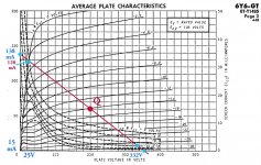
Attachments
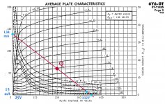

There is an error in my calcs, Imax is 128 mA, not 138 mA. Imax is where the curve for G1 at Zero crosses the 2.6K Loadline. The power output is then 4.34 Watts. And 2H is 9.3%.
More power but at greater 2H is possible by rotating the loadline clockwise. Say to 2K. Plate Dissipation is still OK except on program peaks.
More power but at greater 2H is possible by rotating the loadline clockwise. Say to 2K. Plate Dissipation is still OK except on program peaks.
Attachments
On this schematics posted by Robert appears something similar to what you mean with 12AT7... whoever is interested in following your suggestion can draw it from here, obviously adjusting the voltages. (There is also some NF here).I was curious to discover how close a construction of the operating conditions in graphical form would come to the published performance. Should be in very close agreement.
The operating point (Q) is set at the data sheet numbers, G2 running 135V, the plate at 200V. G1 is set at -14V. The loadline is a slope of 2.6K.
The Max & Min of plate current are 138 mA & 15 mA for a swing of 123 mA.
The Max & Min of plate voltage are 332V & 25V, a swing of307V.
Power output before any losses (the OPT) is (307*0.123) / 8, or 4.72 Watts.
In the same ballpark, anyway.
2H is given by {[(Imax + Imin) / 2] –Io} / (Imax – Imin) all X100% (refer to the attachment)
Stuffing the numbers in we get
{[0.153 /2]- 0.61] / 0.123}……..12.6%
My look at the alternative circuit used a 12AT7 to drive both the 6Y6s. & left the 6V6 in.
As I added the heater currents I was still thinking of a 6BQ7 driver & got 3.35A for the total heater current.😳

Hi,It has two PS because it was born as two separate circuits to have the possibility of using either the preamp or the power amplifier with other circuits... anyway, are you so sure that two smaller PSs weigh so much less than one but more big that needs to be able to deliver 300mA peak and 6A for the filaments? And are you also so sure that it is easily available and, if you find it, it costs much less than two PS that can be easily bought in the oriental market?
I don't understand where you see a few picofarads...
having 2 separate stages - each with its own power supply - is simply a fantastic idea, which few have realised. I plan to make an amplifier like this myself, and not for reasons of economy or to use surplus parts in storage. But precisely to exploit the modularity of the 2 stages to experiment with using different tubes and to appreciate their sonic differences.
Merry Christmas.
Yes, it is. And last but not least, the ease of calculations for the right setting.Hi,
having 2 separate stages - each with its own power supply - is simply a fantastic idea, which few have realised. I plan to make an amplifier like this myself, and not for reasons of economy or to use surplus parts in storage. But precisely to exploit the modularity of the 2 stages to experiment with using different tubes and to appreciate their sonic differences.
Merry Christmas.
Another trick to make the circuit even more elastic is to use a 500 ohm potentiometer in series with a 47 ohm resistor on the 6V6 cathode... this gives the possibility, both to power the Screen of other tubes that require a lower voltage (think for example 6CL6, 6W6, etc...), or use other types of tubes instead of 6V6 (for example, if you only have 9 pins sockets, using a 6BQ5, or similar.
Merry Christmas.

- Home
- Amplifiers
- Tubes / Valves
- 6Y6 SE amplifier - Definitive project