Hello everyone,
I have built two engineer amps from Pete Millett. I have used 6JN6 as output tubes. One of my output tube is now doing runaways. Instead of simply replacing it and re-adjusting the bias, I would like to test the remaining 3 tubes with my uTracer and see where they stand. Then have a documented procedure on how to test my stock of spare 6JN6 tubes.
I'm however not certain what is the correct procedure with the u-tracer. Can someone provide some guidance on how to connect the gazillons of grids and screens, then the parameters I should trace ?
Thanks!
Charles
Hi Charles, this should not be an different to testing any outout tube, except perhaps if you have some special requirement for the supressor grid.
6JN6 data

Pins 4 or 10 are probably connected to the cathode, pin 2, so a link would be needed between those when testing.
Regarding the operating conditions for testing - are you assessing the quality of the tube, or how it behaves in your circuit?
6JN6 data
Pins 4 or 10 are probably connected to the cathode, pin 2, so a link would be needed between those when testing.
Regarding the operating conditions for testing - are you assessing the quality of the tube, or how it behaves in your circuit?
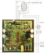
The amp is a push-pull, on the schematics 4 is indeed connected to the cathode. My goal is to "sort out" the tube stock I have an see if they are within their spec before plugin them into the amp and try to bias them. Maybe pair them for similar curves. Unclear to me Pin 5 is the grid for testing if I understand correctly, then 3 goes to some grid voltage. What should I apply there ? A voltage ? Short it somewhere ?
sorry for questions that seems dumb... have been in IT for 30 years so my tube lessons are long gone dark...
sorry for questions that seems dumb... have been in IT for 30 years so my tube lessons are long gone dark...
Pin-5 is not connected to anything, what diagram are you looking at? It's just a pentode, you test it like any pentode in the u-tracer: I(Va, Vg) with Vs, Vh Constant. Is this your first time using it?
Attachments
Last edited:
Thanks Merlinb and OldHector, it's my first pentode measurement with the uTracer, hence my doubts. I was looking at the schematics on http://pmillett.com/DCPP.htm and saw pins 5 and 11 both connected. Now I understand Pete made a PCB that supports other tubes where pin 5 may be needed. For the 6NJ6 it's not.
Seeing your pic and the function you recommend ( I(Va, Vg) with Vs, Vh Constant ), then I suppose I should try to reproduce the red curve from the data sheet ? In Pete's design, the screen is at 150V.

Then about "matching" pairs, in my understanding, I should attempt to find two tubes that have very similar curves for the screen=150V line, correct ?
Another (potentially stupid) question : if a tube is near its life' end, what parameter will deviate and in which way ?
Seeing your pic and the function you recommend ( I(Va, Vg) with Vs, Vh Constant ), then I suppose I should try to reproduce the red curve from the data sheet ? In Pete's design, the screen is at 150V.
Then about "matching" pairs, in my understanding, I should attempt to find two tubes that have very similar curves for the screen=150V line, correct ?
Another (potentially stupid) question : if a tube is near its life' end, what parameter will deviate and in which way ?
Attachments
Yes that sounds reasonable. Set Vs to 150V and you will get a set of G1 curves, the 'top one' corresponding to the one you circled in red. Exactly the same as the first graph in the datasheet you attached.I suppose I should try to reproduce the red curve from the data sheet ? In Pete's design, the screen is at 150V.
YesI should attempt to find two tubes that have very similar curves for the screen=150V line, correct ?
The measured (plate or screen) current will be lower than for a fresh tube.if a tube is near its life' end, what parameter will deviate and in which way ?
That was super helpful, thank you Merlin !
awaiting a spare socket so I can plug in tubes and start measuring. I will comment again when I have some data.
awaiting a spare socket so I can plug in tubes and start measuring. I will comment again when I have some data.
Maybe you should measure with g2 at 150V and varying g1
Then compare with : 6jn6 data sheet and see the diagram on page 3
Then compare with : 6jn6 data sheet and see the diagram on page 3
Yes that's what he said he would do.Maybe you should measure with g2 at 150V and varying g1
The shown graph was g=0 and varying g2. That's my concern.Yes that's what he said he would do.
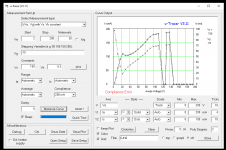
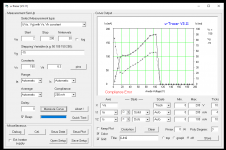
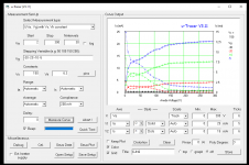
Hello everyone, I'm becoming mad... can't get any senseful measurements. See the 4 attached graphs. Tube 1 is the one having done a runaway and red-plating in the amp. The other 3 tubes always were ok.
I have tried to replicate the measurement type I(Va, Vg) with Vs, Vh constant. You should see it from the attached screen shots, including all the other parameters. VA=2-200, Vg=-15, Vs=150, graph measuring Ia and Is. Tube 1 makes about sense but the currents are very low compared to the reference sheet. Tubes 2, 3 and 4 exhibit "crazy high" currents, it then trigger the compliance limits. It's re-assuring tubes 2-4 are about the same, but the values... not really sane.
I'm sure I'm doing something wrong but I can't figure what. Help welcome !
Attachments

Not sure it will help but I tested my 6JN6s in an attempt to match them for my DCPP using the uTracer. Attached are my outputs from the app. Perhaps the settings will be of use.
I’d make sure your valves aren’t oscillating - that could explain the weird results. Add some ferrites to the connections, close to the pins.
I’d make sure your valves aren’t oscillating - that could explain the weird results. Add some ferrites to the connections, close to the pins.
Attachments
Tanks Christian, oscillation never crossed my mind because I always successfully used my uTracer, but it might well be the case, as I'm using an "external dock" with cables for the Compactron tube, and I neglected the ferrites. I will test end of the week and report. Meanwhile thanks for your reference files, they will help to compare mine!Not sure it will help but I tested my 6JN6s in an attempt to match them for my DCPP using the uTracer. Attached are my outputs from the app. Perhaps the settings will be of use.
I’d make sure your valves aren’t oscillating - that could explain the weird results. Add some ferrites to the connections, close to the pins.
With cables just using ferrite beads may not be enough to prevent oscillation.
Better use grid stopper resistors, 1k for G1, 100 ohm for G2, soldered short and directly to the socket pins.
Better use grid stopper resistors, 1k for G1, 100 ohm for G2, soldered short and directly to the socket pins.
thx for all the hints. I connected 2 + 4 but not 10, I will do so, plus add the stoppers resistors, ferrites and shorter cables. I certainly can do shorter 🙂

Hello again,
it took some time, rewiring, ferrites, grid resistors, etc and so I have measured the existing used tubes, plus my stash. All measured with the quick test (Va=250V, Vs=150V, Vg=-22.5V), measuring Ia and Is. I do have some curves as well, they make sense against the data sheet values. So the changes to my test rig did the job, thanks all for the hints. Now on to measurements.
My uTracer can't go far into Ia, almost all tubes in the 100% area showed compliance errors as the Ia with grid at -10V went over 200mA, triggering the compliance break-up. I didn't want to test over the limits, I have no interest in smoking my uTracer.
First, the existing tubes that were used in the amp for 4 years:
Then I measured my stash of tubes. They are NOS (or so did the shop sold them to me. First 9 RCA :
I'm somewhat surprised by the low values of half of my tubes (worst are RCA 2, 4 and Sylvania 2). The number shown by TristanC above are better, most of his tubes are near nominal values. So I question whether these tubes are new (they should as I bought them from AES (tubesandmore). Or maybe I should let it go and just use them ?
Edit : I tried rising the heater from 6.3 to 6.6 in steps, the Ia/Is rise accordingly, so I think my measuring are maybe ok.
Thanks, Charles
it took some time, rewiring, ferrites, grid resistors, etc and so I have measured the existing used tubes, plus my stash. All measured with the quick test (Va=250V, Vs=150V, Vg=-22.5V), measuring Ia and Is. I do have some curves as well, they make sense against the data sheet values. So the changes to my test rig did the job, thanks all for the hints. Now on to measurements.
My uTracer can't go far into Ia, almost all tubes in the 100% area showed compliance errors as the Ia with grid at -10V went over 200mA, triggering the compliance break-up. I didn't want to test over the limits, I have no interest in smoking my uTracer.
First, the existing tubes that were used in the amp for 4 years:
- 1 : 4/4 %
- 2 : 77/78 %
- 3 : 104/126 %
- 4 : 118/119 %
Then I measured my stash of tubes. They are NOS (or so did the shop sold them to me. First 9 RCA :
- 1 : 97 / 91 %
- 2 : 75 / 65 %
- 3 : 79 / 64 %
- 4 : 64 / 63 %
- 5 : 87 / 89 %
- 6 : 100 / 98 %
- 7 : 82 / 79 %
- 8 : 67 / 125 %
- 9 : 87 / 91 %
- 1 : 96 / 106 %
- 2 : 72 / 74 %
- 3 : 123 / 126 %
- 4 : 89 / 100 %
- 5 : 93 / 99 %
- 6 : 76 / 83 %
I'm somewhat surprised by the low values of half of my tubes (worst are RCA 2, 4 and Sylvania 2). The number shown by TristanC above are better, most of his tubes are near nominal values. So I question whether these tubes are new (they should as I bought them from AES (tubesandmore). Or maybe I should let it go and just use them ?
Edit : I tried rising the heater from 6.3 to 6.6 in steps, the Ia/Is rise accordingly, so I think my measuring are maybe ok.
Thanks, Charles
Attachments

According to the old practices they are all testing 'Good', i.e more than 60% nominal.
Just select similar pairs. If they have not been used for many years I think they can change a bit if low levels of gas are influencing the readings
Just select similar pairs. If they have not been used for many years I think they can change a bit if low levels of gas are influencing the readings
Glad you got it sorted. I matched mine roughly based on current values - looking for the diff between readings of each pair and looking for pairs with minimal diffs. A quick spreadsheet and some =RANK(xxx) type of thing. Since doing that, one valve failed and I swapped it out with one that showed the ‘next closest’ match to the remaining.
- Home
- Amplifiers
- Tubes / Valves
- How to measure a 6JN6 pentode with uTracer