Since I have recently acquired the wonderful Beyma CP755Nd 1.4" drivers, I started planning a large MEH with them. 3 way, single flare (with the option to add a secondary flare). Mids will be 4x Faital Pro 3FE22s and the LF 2 x BC 10CL51s. The LF might be also a single 15" (if it can fit the horn), since I have two Eminence Deltalite II units at my disposal.
The 3D (80 x 60 dispersion) model shows the entry part with driver flange for 3D printing. I yet have to try more options here - it needs to fit my printer. This part can be also left out and replaced by plywood in a more traditional way of building these.

This is going to be a long term project for the next year or two I think🙂
The 3D (80 x 60 dispersion) model shows the entry part with driver flange for 3D printing. I yet have to try more options here - it needs to fit my printer. This part can be also left out and replaced by plywood in a more traditional way of building these.
This is going to be a long term project for the next year or two I think🙂

The project is moving ahead slowly. I am creating a fully parametric model in OpenSCAD for the plywood conical part, so that I can generate the STL or STEP parts with just a few clicks for different sizes, angles and driver mounting options.
I need to measure the influence of the chamber and port on the mid driver to find a good placement for the port holes and then a lot of simulations in Hornresp to define the horn part dimensions.
I need to measure the influence of the chamber and port on the mid driver to find a good placement for the port holes and then a lot of simulations in Hornresp to define the horn part dimensions.
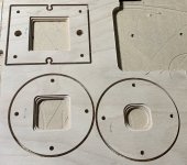
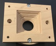
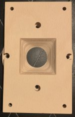
Some teaser pictures from the work in progress🙂
This is the adaptor for 1.4 inch driver to be machined from three layers of 10 mm beech plywood.


And the basic parametric model heavily inspired by @mark100 `s builds.

This is the adaptor for 1.4 inch driver to be machined from three layers of 10 mm beech plywood.
And the basic parametric model heavily inspired by @mark100 `s builds.
Looking good pelanj !
It's cool you can make adapters like that. Not something i know how to do yet.
I'm sure you've figured out the name of the game, with the top-mounted lows, is figuring out the H vs V pattern and overall size of the horn, that let's the drivers fit underneath the lid.
Well, that's been the game for me at least, because i use the lid to seal them in without another box around the entire horn. Just saving weight 🙂
My 36" x 22" syn10's with their 90x60 pattern weigh only 49 lbs ! ---(with 2 10"s, 4 4"s, and CD.)
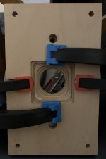
Your way of mounting the woofers was the main driver for making the parametric model - I find it really smart. Now I can try different options and watch for collisions - like the one in the picture. I will do some simulations in Hornresp with suitable woofers to decide later on the final dimensions. It is a long term project, I am still not fully decided if the HF will be a CD or the big Heil AMT. Most probably, I will build both as prototypes from chipboard or OSB and decide based on the outcome.
I think the prototype will use two 4NDF34 and a single 15" - most probably the DeltaLite II 2515 I already have. The pattern will be 80x60 or 90x60, the largest dimension of a single panel is limited by the size of my CNC - ca 80 cm.
Without using any tricks, the largest enclosure that would fit my CNC using 600 mm wide flooring panels would only house a 12" - a 80x70 deg with a mouth of ca 800 x 690 mm. The sealed volume with a 12CL64 will result in Q around 0.8 and fs slightly below 150 Hz with f3 around 125 Hz. Now it is time to feed the numbers to Hornresp.
Since chipboard is still cheaper than new woofers, I will try to accomodate a 15" there with some of the boards made in parts. With some smart positioning, I should be able to use parts of the board that would otherwise get scrapped.
This is how I plan to split the largest boards. I will keep all the other below 800 mm max dimension. That wil allow to fit in a 15". Although the volume seems to be a bit too small for the Deltalite.

I think small volume can keep the low driver from reaching down as far as desired. I found reflex ports on syn8 worked well and were easy to implement.This is how I plan to split the largest boards. I will keep all the other below 800 mm max dimension. That wil allow to fit in a 15". Although the volume seems to be a bit too small for the Deltalite.
View attachment 1118353
(syn8 uses same top and bottom low driver mount strategy)
Here should be the hornresp model of one of the build candidates. HF will be Beyma CP755Nd, mids 4x FaitalPro 3FE22s and LF a single BC 12CL64. I tried to add BR ports, but it did not look like I expected, there was a deep notch - I must have done something wrong there.
Attachments
And now I know what have I done wrong. I was watching Power 3, I should have selected Total Power, where the new "Combined" option appeared🙂 It seems that with the BR, I should be able to reach easily below 100 Hz with a single 12CL64. And I think I will just go for the no-compromise 4NDF34s, unfortunately, to get 4 pieces, I will have to order from abroad, there are only two in stock now in CZ.
Interesting your using open SCAD, I have a pretty silly workflow for calculated shapes involving Octave and a Fusion360 python import script, perhaps I could simplify my workflow. 3FE22 is a decent driver for MEH mid I have been running 4 per side of the ferrite version for PA for a few years and have enough output to keep up with a 15" midbass and 1" comp.
Yes, TLHP will most probably be the source, but I will most probably wait until January anyway.
OpenSCAD is quite handy for the parametric stuff. I found it easier to use than FreeCAD. The script is far from finished and not documented at all, but I can share it for inspiration if someone is interested.
There is a really cool looking library called "Round everything" - I yet have to install it and learn how to use it, but for flat beveled panels produced as STL for machining it is not needed. And another nice thing is, that the project file can be directly imported into FreeCAD as well and one can have a multibody STEP file in no time.
I've been getting the 4NDF34's from TLHP.
I checked the website, and it also has 2NDF26-8 or -16 and 3NDF26-8 or -16. They are probably good for MEH as well.
I also did not give up thinking about the single 15" bass version. I think I found an easy way to add more volume - basically rotate the horn 90 degrees and add a square bottom. The 15" would be mounted from the bottom, the midranges from the top. I wonder if there are any significant drawbacks having the taps placed asymmetrically.
- Home
- Loudspeakers
- Multi-Way
- 3 way MEH with 1.4" CD - 3D print and CNC