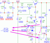
pooge 5.51
I have now built the Pooge 5.51 and ALW's 5.51 revised versions.My only problem is the LED is suppose to stay on but after about 5 seconds,it goes off.Anyone have any suggestions on what could possibly be wrong?
Mike
I have now built the Pooge 5.51 and ALW's 5.51 revised versions.My only problem is the LED is suppose to stay on but after about 5 seconds,it goes off.Anyone have any suggestions on what could possibly be wrong?
Mike
I have the same issue on my implementation of the POOGE Regulator.
The LED goes off after some seconds (after the regulator is stabilized).
Does anyone have some idee?
Alex
The LED goes off after some seconds (after the regulator is stabilized).
Does anyone have some idee?
Alex
Hello,
i did a simulation of Pooge 5.51 reg using the TL431 as a voltage reference. The output voltage is flat as a ruler. What I would like to know, and can't check, is the TL431 properly biased (> = 1mA)?

i did a simulation of Pooge 5.51 reg using the TL431 as a voltage reference. The output voltage is flat as a ruler. What I would like to know, and can't check, is the TL431 properly biased (> = 1mA)?

...What I would like to know, and can't check, is the TL431 properly biased (> = 1mA)?...
Why have a computer if you don't make it *compute* for you?
If your simulator will not report the current in the TL431, then put a 0.0001 Ohm resistor in series and order the simulator to report the current in the resistor.
With the image you give us, it is "possible" to figure the TL431 current but I need all my fingers and toes. X1 is fed by Q2, D5, and R9. (C3 should not pass DC.) D5 current is "n" instead of "u" so is very-very small. So add Q2 current to R9 current.
It looks to me like 0.9mA which does not meet your stated requirement.
WHY is R9 "10k"?? It has NO function except to feed TL431. Many of the specs for TL431 are taken at 10mA. Your load is 400mA, so you can spare 10mA. But say 5mA plus Q2 current. There is 2.5V across R9. We want 5mA. 2.5V/5mA is 500 Ohms. 330, 470, 680, whatever is convenient.
Attachments
POOGE: An acronym for "Progressive Optimization Of Generic Equipment", From the now defunct The Audio Amateur Magazine.
Any reason for not using a 5V reference IC rather than a TL431a? (beginner question - I'm aware there's a cost element in the decision)
TL431 is adjustable in voltage, where a reference IC like REF01 or REF 02 is usually a fixed, trimmed voltage with very no or slight adjustability. Reference ICs also often have a current limit of 20mA or less, where 431 can do a bit more current. Reference ICs may also have a better noise specification as well.
I understand that Pooge stands for "Progressive Optimization Of Generic Equipment". I saw it first used in the now defunct The Audio Amateur Magazine.
Hello. I really like to build this,Ive got nice results with Pooge 5.51 simulation (5V out / 1A current). Attached TinaTI TSC sim file.
PS: For far better results, C4 goes to TL431 voltage reference, not on base of T4.
View attachment 1047959
1.please help with the component value. I cannot understand the resistor and capacitor value.
2. How to set the output voltage to 12 volt?
Please help me. Thank you so much. Doni
The Audio Amateur isn't dead by a long shot.I understand that Pooge stands for "Progressive Optimization Of Generic Equipment". I saw it first used in the now defunct The Audio Amateur Magazine.
Just changed its name to AudioXpress.
Jan
Hi, Jan- I used to get AudioXpress but let the subscription lapse. It seems more oriented towards professional audio reporting and less about The Audio Amateur style of home brewing different projects. AudioXpress is still an excellent magazine, though.
The cowpasiture value, not lightspeed.impedance of cap
In your equation:Xc=1 / (2*pi*f*C) f=the frequency to filter,C=capacitance value or 3.0 x 10(8) m/sec?
Mike
Dimensional analysis can confirm that - farads are equivalent to seconds per ohm, so 1 / ( 1/s * s/ohm) = 1 / ( 1 / ohm) = ohm...
- Home
- Amplifiers
- Solid State
- Pooge 5.51 positive regulator


