You meant solder a diode between pin 3 and 1 or 4 of the 300B? Which diode should I get? Please advise. Thank you!!!OK when you have a cathode follower you would normally place a neon or diode from grid to cathode to stop the tube arcing when cold. Maybe the lack of diode is causing breakdown on the 300B.
OK it does not explain the pop with a fresh set of 300B. But its normal to add across between grid and cathode so the cathode cannot be more negative than the grid. Its normally done with something like a E88CC not a 300B. Can you see any of the valves or anything on the underside flash with the pop with the lights off.
Last edited:
From the valve wizard:
A diode must be added between grid and cathode to prevent arcing between the two electrodes before the heaters have fully warmed up. Once the valve is conducting normally this diode will be reverse-biased and completely off, playing no further part is circuit operation.

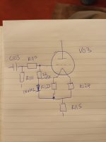
So to confirm, I will solder a diode, IN4002, in the right direction between these two points shown in the schematic....for both 300B. Right?If you want to try just follow the circuit above a IN4002 would do. Probably between grid and the junction of R123, R124, R115. Make sure it's the right way round so it does not conduct when the tubes are warm.
BTW, I have just tested the power down and up again, there is no spark or flash in the chassis and all tubes light up normally.
I can see a problem C103 when the valves are cold is exposed to more then 400V. Adding the diode will make this worse. C103 should be a 630V component. It may be C103 is the source of the pop.
Understood...thanks a lot for help...👍Yep in same direction as #53. Try on pop channel (sorry bad pun). Be careful - make sure it's off - unplug it and voltages have gone before working on it. The Ht and negative rails have bleed resistors but if you have a multimeter/neon screwdriver check.
Will report back.
Actually, I have upgraded C102 n C103 to Jupiter Copper Foil 600V 0.1uf as well as sockets recently...nevertheless, the pop was there before and after. I thought the upgrade will fix the pop issue but didnt.I can see a problem C103 when the valves are cold is exposed to more then 400V. Adding the diode will make this worse. C103 should be a 630V component. It may be C103 is the source of the pop.
Is that ok? Do I still proceed with the diode?
OK so you don't exceed 600V the diode and 47k 1/4W in series with the diode. Draw it on the schematic if you want a check.
Sorry, I lost you there....the diode and 47k 1/4W in series with the diode??? What do you mean? Do I still proceed with the addition of that diode, IN4002?OK so you don't exceed 600V the diode and 47k 1/4W in series with the diode. Draw it on the schematic if you want a check.
Fully understood...Thank you, greatly appreciated!!! I will work on this and get back to report.IN4002 + 22k or 47k in series placed where your green line is. The resistor will limit the voltage that C103 sees.
Yes, will do that definitely. Have just ordered the diode and resistor suggested by @baudouin0. Will report back.Physically tap on the resistors to see if they are cracked slightly.
Again, greatly appreciated for your help....cheers!!!
Just a multimeter and a pen???...lolYep - keep looking I am not sure a cracked resistor or dry joint or something too close to something else are all possibilities. Tapping with a pen is worth a go. What test equipment do you have?
1. Locate the relay J2 and read the part #.How do I check if this is the case? Thanks!!!
If the relay is socketed. You are in luck. Swap the relays (good channel <-> pop channel).
If not, find out the footprint of the relay from datasheet
2. Make sure the amp is completely discharged. That is +B1 and +B2 and other high voltages are all at 0 volt.
You must use a multimeter that is at least 1000V capable to measure the voltages of +B1 and +B2.
Most multimeters are only ~600V capable. You have to build a voltage divider to scale down the voltage for measurements.
3. Measure the resistances of both gangs of J2 (see diagram). Compare the good channel with the "pop channel"
The relay should be normally open (high impedance).
Noted...thank you for the detailed explanation. Will look into it and report back.1. Locate the relay J2 and read the part #.
If the relay is socketed. You are in luck. Swap the relays (good channel <-> pop channel).
If not, find out the footprint of the relay from datasheet
2. Make sure the amp is completely discharged. That is +B1 and +B2 and other high voltages are all at 0 volt.
You must use a multimeter that is at least 1000V capable to measure the voltages of +B1 and +B2.
Most multimeters are only ~600V capable. You have to build a voltage divider to scale down the voltage for measurements.
3. Measure the resistances of both gangs of J2 (see diagram). Compare the good channel with the "pop channel"
The relay should be normally open (high impedance).
View attachment 1117425
If you want to try live soldering a couple of wire across the lowest bleed resistors R59 or R62 and tape them to your multimeter cables. There should be delay of a few seconds before the HT appears. If C27 is leaky then this may have changed. Tantalum cap is better here.
When does the pop appear immediately after turning back on or a delay? Is the channel otherwise the same audio performance as the right? What mods did you make to the amp?
When does the pop appear immediately after turning back on or a delay? Is the channel otherwise the same audio performance as the right? What mods did you make to the amp?
- Home
- Amplifiers
- Tubes / Valves
- Left speaker pops with tube amp