While I was getting idea to use my 8 matched EL84 to a build a monoblock,
https://diyaudioprojects.com/Tubes/EL84-Mini-Block-Amps/
or something like a manely stringray clone
I was wondering how does commerical amplifer desgin their amplifer running the first few(8) Watt run at class A and run at class AB afterwards.
Is there any diy project or scheamtic I can refernce it to ? I am thinking to have the 4 nos of EL84 in push pull parallel runinng at class A in first 8 watts and run at class AB afterwards (maxium to 35W ?).

It's important to note that the Class-A region of a class AB amp, is Push-Pull Class A, and not single-ended Class-A that people hold in such reverence.
It depends on the bias current. As long as either tube conducts, it works in Class-A. After cutoff of one tube, only the other tube delivers output current, this is Class-B operation. Putting these two regions together is called Class-AB1.
If you increase the bias current, there will be more output power in the Class-A region.
If you increase the bias current, there will be more output power in the Class-A region.
It depends on the bias current. As long as either tube conducts, it works in Class-A. After cutoff of one tube, only the other tube delivers output current, this is Class-B operation. Putting these two regions together is called Class-AB1.
If you increase the bias current, there will be more output power in the Class-A region.
Your description of the class A to AB transition to class B is not quite right. It is a common misunderstanding of the definition of class B. There is no class B operation in a class AB biased amp because the definition of class B is to be in cutoff for 180 degrees or more. That cannot be done unless the amp is biased at cutoff, 0 idle current. That is class B and only 1 tube at a time is conducting. So class B is a totally independant class. AB is its own class where the signal cycle in cutoff is less than 180 degrees and both tubes will be in conduction for a time even at full power. Or at lower power will be in class A mode.
How much Class A you can get out of an OP stage design depends as mentioned on bias and AFAIK on the OPT/primary Z. You can only bias a stage so much to run in Class A before you exceed the valves maximum dissipation. Most AB1 stages are biased at about 75% so that the valve is biased so that it doesn't run too hot, there are exceptions though.
There is a design called extended Class A, see - https://www.ampbooks.com/mobile/classic-circuits/extended-a/ where in a paralleled push pull stage one pair of OP valves is biased in Class A, the other pair in cutoff or class B, the idea being that at "normal" listening levels your listening to Class A, the other pair cuts in when more OP power is needed.
Andy.
How much Class A you can get out of an OP stage design depends as mentioned on bias and AFAIK on the OPT/primary Z. You can only bias a stage so much to run in Class A before you exceed the valves maximum dissipation. Most AB1 stages are biased at about 75% so that the valve is biased so that it doesn't run too hot, there are exceptions though.
There is a design called extended Class A, see - https://www.ampbooks.com/mobile/classic-circuits/extended-a/ where in a paralleled push pull stage one pair of OP valves is biased in Class A, the other pair in cutoff or class B, the idea being that at "normal" listening levels your listening to Class A, the other pair cuts in when more OP power is needed.
Andy.
The tubes biased in class B would be in operation even at low signal levels along with the class A tubes when the (+) half of the signal on the grid pulls the class B tubes into conduction. But I'd bet it sounds better than a full class B amp. Not much crossover distortion.
If I remember correctly when I built the extended Class A stage, see attached the "Class B" pair were not conducting at low power, I may be wrong though. The OPT I used wasn't the same as in the design though and there were other parameters that may have been different.
Andy.
Andy.
Attachments
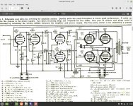
The class B tubes may have been biased really deep and not conducting 180 degrees, very possibly. Large K resistor or high bias voltage deep in cutoff.If I remember correctly when I built the extended Class A stage, see attached the "Class B" pair were not conducting at low power, I may be wrong though. The OPT I used wasn't the same as in the design though and there were other parameters that may have been different.
Andy.
While I was getting idea to use my 8 matched EL84 to a build a monoblock,
https://diyaudioprojects.com/Tubes/EL84-Mini-Block-Amps/
or something like a manely stringray clone
I was wondering how does commerical amplifer desgin their amplifer running the first few(8) Watt run at class A and run at class AB afterwards.
Is there any diy project or scheamtic I can refernce it to ? I am thinking to have the 4 nos of EL84 in push pull parallel runinng at class A in first 8 watts and run at class AB afterwards (maxium to 35W ?).
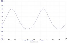
If you put a resistor of 1 ohm ( an example) in series with cathode of 84 you can monitor the ac current and when it leave the class A .
With a proper bias current, p.e., 15 mA of each 84 with this method you can understand how much is the class A; take a care about the load. You can use a simply Ressitor as load and, monitoring thr cathode, you can measure the voltage on load.
With a real load the things are different.
In the photo in attache you can see the monitor of the current on cathode; in this picture the upper (positive) wave is quite perfect but the lower (negative) is not the same ( look at the value); the amp is leaving the class A. In this picture is monitored on raw of the p-p of course
While when it is in a full class A the wave is perfect.
When it reach the max level of signal one end is almost cut.
Walter
Attachments
the definition of class B is to be in cutoff for 180 degrees
Correct.
No. That is class C.or more
Correct.
No. That is class C.
Heeeheee... Well, I'd forgive a few degrees of overbias... no one with a hi-fi tube amp is gonna go into C. And discussion of actually trying to run in B is not realistic.
Any switching amp is Class C .. Some even say they are good soundingHeeeheee... Well, I'd forgive a few degrees of overbias... no one with a hi-fi tube amp is gonna go into C. And discussion of actually trying to run in B is not realistic.
There is little reason to run EL84 any way but HOT, so that they go way past 10W/pair without approaching cutoff.
A Class C amplifier is defined as one that conducts for Less than 180 degrees. The application is RF.
That definition was made before most of us were born.
The old vacuum tube FM stations used a Class C output stage.
The analogy is that you crank a flywheel for less than 180 degrees, and then let the flywheel keep spinning, until it comes around again where you crank it again for less than 180 degrees.
The tube is you pushing the crank, the flywheel is the resonant LC tank at the output.
You can consider the class C amplifier to be the first switching amplifier.
The tube does not dissipate any power when it is cut off.
The tube dissipates very little power when the plate "jumps" through the grid voltage, on its way near to the cathode voltage.
That is why a lot of class C RF triodes are rated for control grid voltages of + 50V, + 100V, etc.
Class C is a completely different world than most of you are used to.
Class C does not work well for Audio (who wants to be tied to a single frequency resonator).
Imagine the musician plays a C scale on the piano, C, D, E, F, G, A, B, C.
But all you hear is C . . . . . . C.
Because of the nature of the signal of the original GSM Phones, they could use class C amplifiers (Class C solid state).
Last edited:
My post #13, what i mean is Class 'D' amps ( not class 'C' ) is sometimes described as good sounding.
Sorry.
Sorry.
Nobody biting yet. Maybe try one more time ;-)My post #13, what i mean is Class 'D' amps ( not class 'C' ) is sometimes described as good sounding.
Sorry.
jan
Class D amplifiers are much like taking the data stream of an SACD, making it really, really big, and then low-passing it to a loudspeaker. It's obvious that the making it really, really big part is going to work a lot differently than the making it really, really big part of a conventional linear amplifier. EXCEPT when you take the total Zen B. Putzeys viewpoint that the amplifying function can be dominated by the feedback network (which can be made arbitrarily faultless) if you work at it.
All good fortune,
Chris
(I bit. You're welcome.)
All good fortune,
Chris
(I bit. You're welcome.)
😎 Bruno's class D amps routinely better the best class A's out there. But most audiophiles live in the past anyway.
All good fortune to you too.
Jan
All good fortune to you too.
Jan
As someone who has daily driven a carbureted car for the last ten years this gave me a chuckle 🙂😎 Bruno's class D amps routinely better the best class A's out there. But most audiophiles live in the past anyway.
All good fortune to you too.
Jan
- Home
- Amplifiers
- Tubes / Valves
- Amplifer first few watt run at class A than class AB