If you do not mind a little bit of distortion,
but you want a very interesting good sound,
then you should revisit this thread.
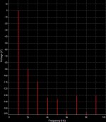
The test shows high value of 2nd harmonic.
This is typical of JFET and MOSFET.
Ask Nelson Pass. He knows!
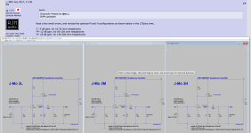
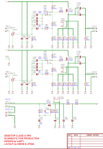
I will be posting the schematic soon.
but you want a very interesting good sound,
then you should revisit this thread.
The test shows high value of 2nd harmonic.
This is typical of JFET and MOSFET.
Ask Nelson Pass. He knows!
I will be posting the schematic soon.


Looks good. But the cap between drain and gate of IRF seems to be too high IMO. There isn't need for those stoppers.
Would't self polarizing the Jfet allow u skip several components? and achieve better PSRR?
I have tested bandwidth. The cap was chosen to make the curve flat. Without overshot.Looks good. But the cap between drain and gate of IRF seems to be too high IMO. There isn't need for those stoppers.
What do you mean?Would't self polarizing the Jfet allow u skip several components? and achieve better PSRR?
Could you tell me more about self polarizing?
Maybe post a schematic.
As tubes, Jfet's can be self-biased (i think thats the term in english). Look at Fig 3.1 and 3.2 at https://sound-au.com/articles/jfet-design.htm#s3 .
At the input of the jfet Vrgate (R1 in the schemattics) just gives u Zin, and Vrgate = Vgs+Vrsource. As Vrgate is 0 (no DC current flows thru the resistor), Vrgate = -Vgs . So, if you choose a Idq = 2ma (2sk170gr), u can see at the datasheet which would be Vgs, and u can assume that would be the Voltage drop at Vrsource (reversed polarity), so u got Idq and the voltage drop so u can calculate the value of Rsource. U can make it a pot to neglect fabrication dispersion.
This way u can not bother about the DC at the gate (it would be 0V, tho an input cap is needed if your source has DC offset), while at the same time, isolating your input device from the PSU.
I'm not entirely sure if that would mess things in your circuit, since i see now that your Rsource is part of the output network...
EDIT : If u want to change Gain without changing your bias u can add a parallel capacitor + potentiometer to Rsource . Since Gain is (gm * Rdrain // Rl) / (1 + gm * Rs) , by doing that, you keep the DC voltage drops (because of the cap), yet u can change the gain as that parallel net will make Rs' = Rs // Pot . Also in this case u keep Zin the same, in ur design i believe R12 affects ur Zin a lot. It may not be a problem if u keep ur sources low Zout tho.
U may know all of this, but thats what i meant by self polarizing
Last edited:
Would't self polarizing the Jfet allow u skip several components? and achieve better PSRR?
Now I see what you mean.As tubes, Jfet's can be self-biased (i think thats the term in english). Look at Fig 3.1 and 3.2 at https://sound-au.com/articles/jfet-design.htm#s3 .
At the input of the jfet Vrgate (R1 in the schemattics) just gives u Zin, and Vrgate = Vgs+Vrsource. As Vrgate is 0 (no DC current flows thru the resistor), Vrgate = -Vgs . So, if you choose a Idq = 2ma (2sk170gr), u can see at the datasheet which would be Vgs, and u can assume that would be the Voltage drop at Vrsource (reversed polarity), so u got Idq and the voltage drop so u can calculate the value of Rsource. U can make it a pot to neglect fabrication dispersion.
This way u can not bother about the DC at the gate (it would be 0V, tho an input cap is needed if your source has DC offset), while at the same time, isolating your input device from the PSU.
I'm not entirely sure if that would mess things in your circuit, since i see now that your Rsource is part of the output network...
EDIT : If u want to change Gain without changing your bias u can add a parallel capacitor + potentiometer to Rsource . Since Gain is (gm * Rdrain // Rl) / (1 + gm * Rs) , by doing that, you keep the DC voltage drops (because of the cap), yet u can change the gain as that parallel net will make Rs' = Rs // Pot . Also in this case u keep Zin the same, in ur design i believe R12 affects ur Zin a lot. It may not be a problem if u keep ur sources low Zout tho.
U may know all of this, but thats what i meant by self polarizing
I might try to make such a version.
Not sure it can be done.
🙂 Stefan
- Home
- Amplifiers
- Headphone Systems
- JFET + MOSFET Well Sounding Headphone Amp