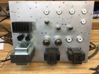
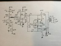
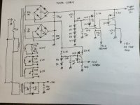
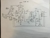
Since the new home build was delayed due to weather, I‘ve gotten this back out of mothballs. The original version was going to use the 6LR8/LU8 tri-pents for outputs, but I had trouble making a decently balanced LTP phase splitter with the triodes. Even with a CCS it still wanted to shove most of the current to one side or the other. The dual triodes were far easier to balance. Spent the rainy morning and most of the afternoon dialing in the frequency compensation. Turns out that 200 pF across the g1 resistor is pretty critical with a 40 mu phase splitter. The Miller capacitance of the splitter working against that resistor was eating too much phase margin. No more snivets and the square wave just has a bit of overshoot.
This one is going to have balanced ins and tone controls, hence the unused (for now) sockets. Got a bunch more of those 6BQ7’s. Might try 6JW8’s for the Baxandall circuit. Pentode gain stage, triode output follower with a boot strap for the plate load. Might look a lot more like an ‘ideal’ inverting op amp.
This one is going to have balanced ins and tone controls, hence the unused (for now) sockets. Got a bunch more of those 6BQ7’s. Might try 6JW8’s for the Baxandall circuit. Pentode gain stage, triode output follower with a boot strap for the plate load. Might look a lot more like an ‘ideal’ inverting op amp.
Attachments
Pentodes and double units are quite good for ltp. The problem for a good performance is the screen grid supply.
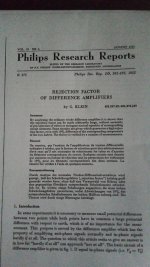
I undestand that you already went to triodes, but I did pentodes as ltp wirh sucessfeul behavior. I read an intersant article from Philips Technical Magazines about it. Let me some minutes to search it.
I undestand that you already went to triodes, but I did pentodes as ltp wirh sucessfeul behavior. I read an intersant article from Philips Technical Magazines about it. Let me some minutes to search it.
It wasn’t the pentodes I was having trouble with. The 6LU8 output pentodes were pretty consistent. It was the “free” 12AT7-like triode in the bottle that was all over the map. So much that I had trouble matching the AC voltages at the plates within 20% making an LTP out of a pair of them. Scratch that. Using a double triode it dialed right in like it usually does. The 10JA5 is the same pentode, just no free triode. When I wound that power trafo I had both 10.5 and 6.3 volt taps on that winding because I was waffling on which tube set to use. This sort of made the decision for me. The other set will get used for something else - probably using one of the triodes as a concertina and the other for gain.
Why do you use a 475k g1 resistor? Would nomally expect 0-1k in this position (e.g. Mullard 5-10 and 5-20).Turns out that 200 pF across the g1 resistor is pretty critical with a 40 mu phase splitter. The Miller capacitance of the splitter working against that resistor was eating too much phase margin. No more snivets and the square wave just has a bit of overshoot.
It's a grid leak, not a stopper, one end is grounded.Why do you use a 475k g1 resistor? Would nomally expect 0-1k in this position (e.g. Mullard 5-10 and 5-20).
Pat Turner was a fan of EL84's as LTP/drivers in some of his big amps, thanks for that article.
Andy.
The sweep tubes and compactrons are great tubes to play with. I made a li'l spud amp with the 6LR8. I do recall that the triode section was ... a triode and that's about it. It definitely wanted to run an an operating point that was quite different from what the data sheet would suggest. Sourcing sockets for the NOVAR tubes was a pain, though. Most sockets out there were for NOVAL. The 12-pin tubes are a bit easier to find sockets for so the 6LU8 would be my choice.
Also see the sticky thread on sweep tubes: https://www.diyaudio.com/community/threads/those-magnificent-television-tubes.211254/
Tom
Also see the sticky thread on sweep tubes: https://www.diyaudio.com/community/threads/those-magnificent-television-tubes.211254/
Tom
I would say the other 475k (to the second triode grid) is a grid leak, but not the one to the first triode grid. Mullard have no resistor to the first grid, it's connected directly to the preceding plate (R10 is the grid leak here).It's a grid leak, not a stopper, one end is grounded.
So the 475k and 200pF are to get good square waves? IIRC Morgan Jones discusses this in "Building valve amplifiers", and for the LTP he uses the RC zobel network between the two plates?
Found it, page 295 of "Building valve amplifiers".
Found it, page 295 of "Building valve amplifiers".
To keep them the same - so the proper phase could be obtained just by moving the bypass cap from one grid to the other. Who the hell knows what the OPT transformer phase is, till you put in a signal and measure the amp or see if it oscillates or not when closing the loop. Get it backwards you move one stinking cap. If the OPT were new you’d just leave the leads long, but these were a salvage job.Why do you use a 475k g1 resistor? Would nomally expect 0-1k in this position (e.g. Mullard 5-10 and 5-20).
Its not “the way everybody else does it”, then you have to figure why it doesn’t work as expected. Massive ringing half way across a 2kHz square wave pulse. Snivets on a quarter of the waveform when driving at low frequency. Now where could I be picking up some excess phase….. and I seem to have found it. At least some of it. Last Mullard I did just had the one grid leak, but I had a brand new Hammond OPT so the phase was figured on the output quad. Got it right the first time anyway.
Interesting - nice one tube per channel. I like the LR8’s because the RCA’s are pretty. Sylvania would be too. The tip-on-top looks better than a bald head on top, but I only have the four LR8’s in my stash and larger quantity of LU8’s to play with. And better quality 12 pin sockets than the handful of novars, as well as the 10JA5 backup approach. So that sort of dictated the starting points. The point of this project was to use all TV tubes to use this set of output iron (from an old 7591 Fisher) and the custom power trafo I made out of an old 36VCT/6A Stancor specifically to get the maximum use of said output iron. I’ll pick up the LR8/LU8 again on another project. Not something where I’m trying to get two gain stages plus the outputs into a global NFB loop.The sweep tubes and compactrons are great tubes to play with. I made a li'l spud amp with the 6LR8. I do recall that the triode section was ... a triode and that's about it. It definitely wanted to run an an operating point that was quite different from what the data sheet would suggest. Sourcing sockets for the NOVAR tubes was a pain, though. Most sockets out there were for NOVAL. The 12-pin tubes are a bit easier to find sockets for so the 6LU8 would be my choice.
Also see the sticky thread on sweep tubes: https://www.diyaudio.com/community/threads/those-magnificent-television-tubes.211254/
Tom
Ive gotten quite a few ideas (including some very “bad” ones) out of that TV tube sticky thread. I go back all the time and I still haven’t seen all of it.
Now I undestand why the 475k "grid stopper", indeed, only resolder the cap to change phase. Still, now that you know the phase is correct, wouldn't it be easier to replace it with some <1k grid stopper and omit the 200pF cap?
About the TV tubes... some 15 years ago I bought about 40x 17KV6 for little money (also 22JF6, 25DQ6B...). Now I finally put them to use, in an OTL amplifier for a line array with a total impedance of 72 ohms, where a pair puts out 10W. The 25DQ6B go in a normal PP amplifier. It gives me great satisfaction to actually use the stuff I have been carrying around in the several moves I did in the last 14 years 🙂
I hope you can soon get back to working on your new house!
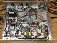
The house project is simply going to be on hold til it quits raining. For long enough to get dump trucks onto the site - which might be next July. Can get a couple of tube amps working in that time. Started on the front end this evening. It’s got a couple of the building blocks I’ll need for a massive 20-some-odd tube preamp that’s been in planning for a while.
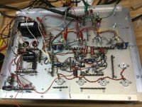
The OPTs in this thing we’re something I picked up my first year of college (1985). They were used in a couple things over the years, but nothing that really performed well so it never stated together permanently. Getting a lot lower distortion out of this, and more than 20 watts - and it’s not motorboating.
The OPTs in this thing we’re something I picked up my first year of college (1985). They were used in a couple things over the years, but nothing that really performed well so it never stated together permanently. Getting a lot lower distortion out of this, and more than 20 watts - and it’s not motorboating.
Just wondering, Why the need for LTP? I find cathodyne works fine in my amps.
EDIT: If it has balanced in, why do you need a phase splitter at all?
EDIT: If it has balanced in, why do you need a phase splitter at all?
Cathodynes work fine - but I wanted two gain stages ahead of the finals. Experiments two or three years ago with these OPTs in a Williamson resulted in uncontrolled motor boating. Even applying all the tricks I used in the big mono blocks didn’t solve it.
The balanced ins aren’t kept all the way through. It’s my band aid for avoiding the use of a pair of $65 input transformers for breaking ground loops. This was supposed to be “cheap”. Simply do not carry the audio return on the safety ground and you never battle the hum. ALL of my SS amps have differential inputs even if it’s not set up as “balanced”. The source I use in the shop has balanced outs anyway, but not everything in the house does. From there it will go to bass and treble controls - I do like those with smaller amps/speakers. Hard to keep those balanced all the way thru for sure. That part is still under construction - the power section was running unbal to get it debugged. Which isn’t a problem if the chassis isn’t grounded yet.
The balanced ins aren’t kept all the way through. It’s my band aid for avoiding the use of a pair of $65 input transformers for breaking ground loops. This was supposed to be “cheap”. Simply do not carry the audio return on the safety ground and you never battle the hum. ALL of my SS amps have differential inputs even if it’s not set up as “balanced”. The source I use in the shop has balanced outs anyway, but not everything in the house does. From there it will go to bass and treble controls - I do like those with smaller amps/speakers. Hard to keep those balanced all the way thru for sure. That part is still under construction - the power section was running unbal to get it debugged. Which isn’t a problem if the chassis isn’t grounded yet.
Makes sense... I make a board using Triad TY250P that costs about 20$... You can also use AD/DA... I use an AD to make a variable optical out, and a DA on the other end. Total cost is like 35$.
I solved motorboating in my design by making the pole between PI and driver lower, and adding 2nd order high pass to the input. On one amp (KT88 using Edcor transformers someome is building from a set of my boards) they had to reduce the amount of gNFB to stabilize it. (changed 2K>68R to 3K>68R)
From VA to PI, Fc= 1.4Hz, From PI to driver, it's 0.3Hz, and from driver to outputs, it's 1.6Hz.
Before, when the Fc points were higher, the amp would "breathe"...
Those little Triads are fine if you drive from a 200 ohm output off a piece of pro gear, but not so good in the general case of 10k impedances. The one I built for bass guitar duty uses one on its “PA” input. It will never get connected directly off a Sony CD player, and if sub-40 is attenuated so what.
I tried everything to get that little Williamson stable. Only thing that worked was making one of the coupling caps 1000 pF resulting in No Bass. Those 10k trafos just dont have enough primary inductance. My big 200 watters almost worked the first time - about 3 seconds of settling time with no special treatment. That 1650W is pretty damn good. I cut the amount of NFB at sub-sonic frequency by introducing a zero in the feedback, and restored square wave response with a single low frequency pole outside the feedback. Quieted right down. That did not work with this transformer set running any set of “audio” output tubes as pentodes. I got it down to fractional hertz, and then gave up and pulled the chassis apart. “When it gets re-done, it’s going Mullard“ so here we are.
Around the same time I wound up another power trafo (bigger 300+ watt) to make proper use of the EL34’s in an ultra linear. Debating whether to go ahead and order OPTs or to wait till after the move. Not really supposed to be “spending money on any of this” right now. Half a dozen other possibilities right now, without spending another dime.
It is now working - properly - and making music in the shop. Measured power both channels sine wave is right at 25 watts per channel. Right now running it through a pair of 10” vocal wedges. I still need to build the wooden base, but that can happen when I get out the saw to build the speakers intended for it (next project in line, a 10” sealed-box 3 way).
The planned speaker system will be Dayton 10” aluminum cones (the old classic ones), wide-band 5” mids, and MDT40’s. All stuff on hand. Design criteria will be to try to keep the impedance reasonably flat, other than the bass peak about 55 Hz for a pop/rock music peak when used with high Z-out amps. This one is still pretty low - should be in the fractional-ohms with the 29 dB of feedback. I had a similar speaker system once using 3rd order Butterworth filters which kept the impedance curve relatively flat. This be an updated version.
6BQ7 input diff amp/buffer, 6JW8 Baxandall tone controls, 6BQ7 power amp gain stage and phase splitter, 10JA5 output tubes. Old Fisher salvaged OPTs. Sounds pretty sweet for not having a single ”audio” tube anywhere in the lineup. The only issue I hear is more noise (hiss) than I’d like with the volume all the way up an no signal. It will be less with the 85dB/W speakers than with the 98dB/W Delta 10’s. I may also try tube rolling the input buffer stage - it runs off a CCS so the bias will just end up where it needs to be, even with vg1 changes. There are lots of other TV tuner cascode types to try. It did take a couple extra 100-ish pF caps to beat down the FM radio signals I was still picking up, courtesy of the higher frequency tubes and PTP wiring. The initial oscillation problems may very well have been initiated by the RF pickup. Nothing was actually demodulating and “talking” through the speakers, but I could see the speech patterns in the 100 ish MHz signal on the scope.
Attachments
-
 6C201B5D-609E-4E03-BC25-F6E48EA1B2A0.jpeg70 KB · Views: 89
 -
 270D819E-C14B-4E5D-AEE9-BA53B9F5A08E.jpeg66.2 KB · Views: 96
 -
 83A3A2F2-C864-4065-9D64-E8B559D5E2F9.jpeg66.6 KB · Views: 87
 -
 B825431C-39F5-47F3-BFC0-0A9ED152381F.jpeg125.6 KB · Views: 80
 -
 EBD5C714-A247-4E69-A887-5439747257C3.jpeg93 KB · Views: 86

- Home
- Amplifiers
- Tubes / Valves
- A little something to pass the time - TV tubes