I have some of the smd 10M45 chips but have not got around to using them yet.
My idea was to mount them on the outer edge of the ground plane (back surface) of a prototype board by using a dremel to grind away copper and make an isolated mounting pad, then solder the tab to the board for heat sinking. The legs should extend over the edge so they can be soldered to.
I do this with fixed voltage TO-252-3 regulators without a problem. Only difference with a 10M45 or 10M90 would be isolating the mounting pad and making sure it is big enough to sink the heat created.
Win W5JAG

Yes, its a shame more people are not exposed to the TSE and SSE, due to the 10Mxx chips. Damn fine amps, both of them.Thanks for looking and look forward to what you find. It just caught my interest on what others can use to keep building your two popular builds. Shame now 10M90S' are not available as well as the 10M45s'.
I run two TSEs active with Altecs and there's not a hint of hiss or hum with 98dB. For a second pair, I'm building SSEs to run active the same way. These amps put an Elekit TU-8200 to shame 🙂
A mosfet that can handle the high tube voltages could possible be use as a constant current source like the 1045S chips. George said he has some IXTP1R6N100D2 in stock and will try them in the next few days. Look forward to hearing what he thinks. I am sure it will work if it can handle the startup surge. That is if the specs are accurate.
It must be a depletion mode N channel mosfet. I have 3 or 4 likely candidates to try, and the TSE-II is back on the bench.A mosfet that can handle the high tube voltages could possible be use as a constant current source like the 1045S chips.
Unfortunately, there are Christmas decorations scattered all over the house and yard and we are having guests for the Thanksgiving holiday this weekend. I'm sure I'll get dragged into at least one Black Friday shopping event as well. I'll try to fire up the TSE-II after I get done hanging lights outside in the 25 degree (F) weather.
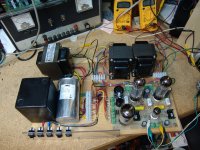
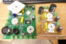
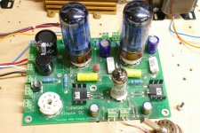
After realizing that messing with a TSE-II board involves risking one of the two working boards that I have, one or more 5842's and one or more expensive DHT's. I decided to take the TSE-II off the bench and put an SSE board in its place. Killing a 12AT7 or 6L6 type won't bother me much since I have plenty of both, so I looked into the "box of broken dreams" for a usable SSE board and found an old friend. This board is dirty. I can remember using it for lots of experiments dating back 10 years or more. It has the Advanced Circuits logo on it with a 2306 date code. That makes it one of the first 50 SSE boards, since I switched board vendors after the first batch. Both of the cathode bypass caps have been swapped to 100 volt parts, so this board was used for my white hot 6BQ6GT test which caused both of the 63 volt caps to explode. The date on those pictures is May 30, 2006.
The coupling cap on the right tube has a burn mark in it in the picture. So does the cap on the board I just found, so this board is one of the first SSE's built. This led me to look further into my old pictures where I found photos of my original test fixture for testing newly built home cooked boards. This was from a time period where I made home cooked boards, populated them, tested them thoroughly, then made an amp and sold it. Once I had the confidence to blow about $700 on a batch of boards, the real SSE was born. Fifteen pictures later in the same folder production quality board number 1 sits in that test fixture. After careful examination I realize that the crusty board I just found is SSE#1. It now has a large septar socket on top of the octal socket on the right side. I remember testing some 4D32's in an SSE, but I can't find the picture, which would provide the date that this board was last used. Its been sleeping in a box for a long time. I did find some rare WE367A's which got tested in this board also by stacking a test socket on top of the on board socket.
Edit: It looks like this board was also used for the SPUD / Furball amp experiment as the burn spot on the coupling cap is present in those pictures too. This led to another PC board that's also in the "box of broken dreams", the one off Spud SE.
I am going to fire this board up, fix it if needed and use it to test some 10M45 alternatives.
Attachments
-
 6BQ6GA_cranked.jpg87.4 KB · Views: 155
 -
 DSC05321.JPG574 KB · Views: 145
 -
 DSC05336.JPG539.8 KB · Views: 141
 -
 WE367A.jpg286.4 KB · Views: 146
 -
 DSC09492.JPG501.4 KB · Views: 150
 -
 P4000593-x.jpg216.4 KB · Views: 143
 -
 DSC09555.JPG493.3 KB · Views: 134
 -
 DSC09575.JPG454.1 KB · Views: 148
 -
 P4000594.JPG389.3 KB · Views: 146
Last edited:
Better run that board through the dishwasher.
I recall seeing the septar socket first appear in the thread about running 6146 in the SSE. I'm thinking 2015 ish?
edit: Holy Toledo - 2010
Win W5JAG
I recall seeing the septar socket first appear in the thread about running 6146 in the SSE. I'm thinking 2015 ish?
edit: Holy Toledo - 2010
Win W5JAG
I almost tried it back when you first told me that trick, but this board stunk of exploded electrolytic goo and I did not want to get that stuff into the dishwasher. I cleaned it up with WD40 and rubbing alcohol, and it lived on for lots more tricks. The WD40 residue is probably why this board is so dusty.Better run that board through the dishwasher.
I found another picture of #1, this time running some tasty old RCA grey glass 6V6GT's. It's from Oct 2008.
DING - DING - DING, I just found it. In between some pictures of bad A$$ Hemis, and a DIY TV antenna. The date is March 28, 2009.
Attachments


That old SSE board that I knocked the octal sockets out of is collecting dust in the storage room at my office - it's due for trip number three or four through the dishwasher.
Win W5JAG
Win W5JAG
Thanks for trying to keep the SSE with a CCS on the pre alive until the time when parts are available again. Putting your Tubelab site where it is now is not the best place or the easiest to find for those that may be interested in building this amplifier with a board. Such is the case though until something is done to make vendors easier to access on this site.I am going to fire this board up, fix it if needed and use it to test some 10M45 alternatives.
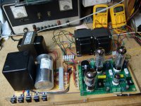
I'm posting this in response to a PM. No, the 6146 is not being used as a rectifier. It was stuck into the socket for a comparison to show the size of the 4D32. The board was powered with an external power supply. Without a power transformer or choke the rectifier socket sees no voltage.
The 4D32's did not work well in the cathode biased SSE. I think that they might work well in A2, but I never tried them in a TSE or TSE-II. They are on my list of tubes to try in the UNSET though.
The 4D32's did not work well in the cathode biased SSE. I think that they might work well in A2, but I never tried them in a TSE or TSE-II. They are on my list of tubes to try in the UNSET though.
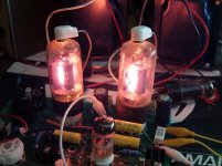
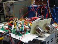
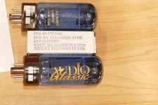
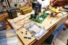
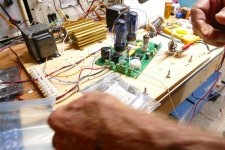
Its Alive. I popped some NOS "Audio Glassic" 6L6WGB's and a NOS mil spec JAN 12AT7WC into SSE #1, connected up a volume pot and a set of 3K ohm Transcendars which were wired for 6000 ohms, hooked it up to my old Knight Kit power supply turned all the way up (452 volts), popped in a CD, pressed play, and .......nothing but silence. A few seconds with a voltmeter told me that the 12AT7 was not conducting at all. I pulled it, sprayed some WD40 into the socket, reinserted the tube and all is well. It's currently on its third CD, Tycho's Simulcast. Soon the parts swapping will commence.
Attachments
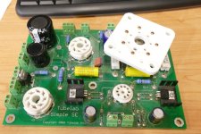
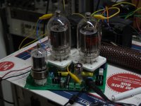
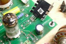
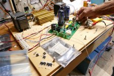
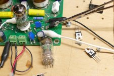
I pulled the 10M45S from the right channel then cleared the holes with a solder sucker. I screwed an IXTP1R6N100D2 to the first heat sink I could find then simply stuck the pins into the holes in the board without soldering. No other parts were changed. What happened when I turned the power back on?
The power supply has a power switch and a HV switch, so I left the power on so the tube heaters were hot. As soon as I flipped the HV switch, Tycho came from BOTH speakers. The 12AT7 half in the left (unchanged) channel was still getting 8.1 mA. The 12AT7 half in the right channel with the 1R6N100D2 is running at 9.6 mA. Perhaps a 360 ohm in place of the 330 would bring it down a bit. I'm going to try some different mosfets before swapping resistors.
The power supply has a power switch and a HV switch, so I left the power on so the tube heaters were hot. As soon as I flipped the HV switch, Tycho came from BOTH speakers. The 12AT7 half in the left (unchanged) channel was still getting 8.1 mA. The 12AT7 half in the right channel with the 1R6N100D2 is running at 9.6 mA. Perhaps a 360 ohm in place of the 330 would bring it down a bit. I'm going to try some different mosfets before swapping resistors.
Attachments
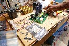
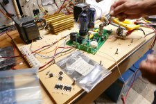
So, I got this stupid idea.........What would happen if I simply yanked the mosfet from the board and stuck in a different one while the amp was on and playing? Apart from the fact that I was about to grab a heat sink with 452 volts on it, what could go wrong? I had already wiggled then removed and replaced the 12AT7 with the power on, with nothing but a few loud pops, so I made sure that I was standing on two layers of insulation with no path for current flow and touched the heat sink. Nothing bad happened, so I grabbed it and pulled the mosfet from the board. Of course the right channel went silent. I stuck it back in and the music resumed. The plan worked, so I went through 32 mosfets, all live swapped. All worked!
I have 10 of the IXTP1R6N100D2 parts, so I tried them all. All were between 9.2 and 9.6 mA except for one which repeatedly gave 12.6 mA, but sounded fine.
I have 10 IXTP08N100D2's so I tried all of them too. Allwere between 7.2 and 8.1 mA.
I have 8 IXTP3N100D2's and all of them worked as well. All were between 8.1 and 8.9 mA.
I have 4 IXTP01N100D parts, and they all worked producing between 6.8 and 7.2 mA.
Since all of the parts in a given bag are grouped rather well, maybe I static zapped the 12.6 mA fet, or maybe it's just an outlier. I have seen some outliers with the 10M45S parts and every batch of them is different.
I'm going to go through my parts stash to see if there are any more "test subjects."
Attachments


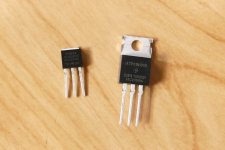
This little guy works too. I only tried one and it got hot pretty quickly with no heat sink. It produced 7.6 mA which increased a few tenths as it got hot. A clip on heat sink or soldering it to a piece of copper would be needed in an amp. The part number is IXTU02N50D and Digikey has 60 of them in stock. TO220 part shown for size comparison.
Attachments
I have seen that as well. For the UNSET I had a bag of about 15 10M45S parts and tested them all to find pairs that were closest. A few were outliers....Since all of the parts in a given bag are grouped rather well, maybe I static zapped the 12.6 mA fet, or maybe it's just an outlier. I have seen some outliers with the 10M45S parts and every batch of them is different...
I have 6 of the 10M45S in TO-220 package if anyone would like to purchase them off me for $4 each + shipping. Please PM if interested.
Many thanks for doing this work. Old parts get obsolete real fast especially discrete parts but there has been some development in those high voltage mosfets the last decade or so. If they can survive the voltage surge on startup they should work fine as a CCS in a tube circuit. Never know for sure though until you do the work George has just done. It would be a shame this design cannot survive for a few more decades for diyer's to build.This little guy works too. I only tried one and it got hot pretty quickly with no heat sink. It produced 7.6 mA which increased a few tenths as it got hot. A clip on heat sink or soldering it to a piece of copper would be needed in an amp. The part number is IXTU02N50D and Digikey has 60 of them in stock. TO220 part shown for size comparison.
Some new project maybe is what Tubelab.com needs to become profitable again. I like the idea of a really good PP EL-84 amplifier. Especially since I have been reading some on Roger Modjeski's getting 40 watts from a PP EL-84 amplifier. Takes high voltage but from what a few geeks like myself have discussed is accomplished with a voltage doubler in the PS section. 700v's on the plates with 350 on the screens. I was not sure a voltage doubler would provide enough current but others on another site believe it would. Sure sounds good getting 40 watts from a PP EL-84 amplifier. If Roger could do it so could others.
The next few days will be rather hectic here, but if I can find the time, I plan to test the THD and frequency response variations (if any) of all the fets previously tested for functionality plus some 10M45 and 10M90 as control subjects. I should have some DN2540's here somewhere, but I haven't found them yet.
Tubelab Inc has never been "profitable" since I will use all the "profit" made in each year to fund the exploration needed to find new ways to blow stuff up and occasionally invent something new like UNSET. There is a vacuum tube based music synthesizer in the works, but progress has been rather slow lately.
The market for PP EL-84 amps is already quite crowded and the existing SPP is by far the slowest moving board I sell, with the exception of a few short bursts around someone's published build of one. I'm more likely to do a PP build with octal tubes or finish the 50+ WPC project that uses one SSE board per channel. I heard about Roger Modjeski's 700 volt EL84 amps several years ago. Powerful, yes. Reliable? Unfortunately, there is lots of "stuff" being sold as EL84's these days and some of them can't even hack 350 volts. I wouldn't trust most 9 pin sockets at 700 volts either. The tube and socket will see twice the B+ voltage in normal operation and 4 to 5 X the B+ voltage if the amp is driven to clipping into a reactive load like a speaker. I have measured over 2500 volts on a 6L6GC based guitar amp running on 430 volts of B+ into a guitar speaker near resonance.
It is also possible to take an ordinary SPP board, or any EL84 amp of a similar design (SY's RLD or one of Morgan Jones' EL84 amps) run the screens at about 200 volts and the plates at 430 volts and get over 30 WPC with a 6600 ohm OPT. The only tubes that survived this abuse were old Sylvania 6BQ5's and JJ EL84's from about 14 years ago. I built a guitar amp with an SPP board that did this and used both channels in parallel for over 60 watts. I played it for about a year with no failures, but wound up robbing it for its built SPP board when I created a push pull amp with KT88's in a SSE board that made more power that sounded better cranked.
Last night I ran some experiments on the old SSE board. I tried running THD and frequency response measurements on the complete amp while live swapping parts again. I came to two conclusions.
Live swapping parts successfully converted another good IXTP1R6N100D2 into a 12.5 mA source. I also fried two 10M45's in the same manner. A bit of thinking and some simple voltage measurements let me realize that these parts are shorted as 12.5 mA is the current seen with a jumper wire in place of the CCS. Yes, the amp still works and sounds OK without the CCS, but the gain is considerably lower. The thinking part let me know that if the gate pin were to make contact first, then either the source or drain made contact next, the gate would be subjected to about 400 volts, turning its oxide layer back to sand. No more live swapping, which considerably slows the testing.
Testing the complete amp masks small changes in the distortion made in the driver stage since the output stage is the dominant source of THD. I connected the driver stage directly to the input of my HP8903A which is also not ideal due to the relatively low input impedance of the 8903A. This led to a THD measurement in the 0.95% range with the original 10M45 chip in the board and the HP 204D audio oscillator set to the same level that drove the complete amp to the edge of clipping. This gets about 40 volts P-P out of the driver.
I then ran through two or three of each mosfet, about a dozen 10M45's (killing one) and three 10M90's. All produced between 0.9 and 1.06 % THD and no significant differences between any of the parts were seen at 20 KHz though there was significant loss at 20 KHz, probably due to loading.
Could we do better?
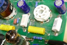
I removed the 220 ohm cathode resistor, and the 331 ohm current set resistor, tested them since they were both discolored, and they were fine. Both were replaced with 10 turn 500 ohm pots. I put a meter on the plate voltage, and another across the 10K resistor to measure tube current. I tried each candidate part with two different NOS MIL Spec tubes, the previously mentioned JAN 12AT7WC (box plate like a 12AX7) and a JAN 6201 / 12AT7WC (folded plate typical in 12AT7's). Both pots were tweaked for minimum THD at 40 volts P-P output on the scope Every part could be adjusted into the 0.81 to 0.92% THD range. The 10M90's both hit the lowest 0.81 and 0.83% spot, while the newer 10M45's were around 0.9%. The original 10M45 became dead as did another IXTP1R6N100D2, so live swapping was abandoned.
For all parts the best performance with the 12AT7WC tube came with about 9.0 to 9.5 mA and 300 volts on the plate. This is over the 2.5 watt maximum plate dissipation level. The 6201 liked 8.5 to 9.2 mA and about 290 volts, again a bit hot.
I reinstalled the output tube and did some testing on the complete amp. In all cases the HF response was only a few tenths of a dB lower at 20 KHz than at 1 KHz, so the rolloff seen in driver only testing was due to the 100K in parallel with 330pF plus cable input impedance of the 8903A.
This morning I noticed a confounder not seen last night. There is a 180K resistor soldered across the 220K grid leak resistor on the output tube putting the measured grid to ground resistance at 99K ohms. I likely did this trying to make the 4D32 tube work. This plus the audio analyzer load is pretty far below what the driver would see in real life operation. The relative data is good (all tested fets will work in the amp) but the absolute voltage and current "best operating points" are not representative of what a real world amp will see. I may remove the resistor and try to tune the complete amp for best performance, but it won't happen today, I have grandkid chasing duty today, and tomorrow will likely involve a mall, Walmart, or something else equally "entertaining."
Live swapping parts successfully converted another good IXTP1R6N100D2 into a 12.5 mA source. I also fried two 10M45's in the same manner. A bit of thinking and some simple voltage measurements let me realize that these parts are shorted as 12.5 mA is the current seen with a jumper wire in place of the CCS. Yes, the amp still works and sounds OK without the CCS, but the gain is considerably lower. The thinking part let me know that if the gate pin were to make contact first, then either the source or drain made contact next, the gate would be subjected to about 400 volts, turning its oxide layer back to sand. No more live swapping, which considerably slows the testing.
Testing the complete amp masks small changes in the distortion made in the driver stage since the output stage is the dominant source of THD. I connected the driver stage directly to the input of my HP8903A which is also not ideal due to the relatively low input impedance of the 8903A. This led to a THD measurement in the 0.95% range with the original 10M45 chip in the board and the HP 204D audio oscillator set to the same level that drove the complete amp to the edge of clipping. This gets about 40 volts P-P out of the driver.
I then ran through two or three of each mosfet, about a dozen 10M45's (killing one) and three 10M90's. All produced between 0.9 and 1.06 % THD and no significant differences between any of the parts were seen at 20 KHz though there was significant loss at 20 KHz, probably due to loading.
Could we do better?
I removed the 220 ohm cathode resistor, and the 331 ohm current set resistor, tested them since they were both discolored, and they were fine. Both were replaced with 10 turn 500 ohm pots. I put a meter on the plate voltage, and another across the 10K resistor to measure tube current. I tried each candidate part with two different NOS MIL Spec tubes, the previously mentioned JAN 12AT7WC (box plate like a 12AX7) and a JAN 6201 / 12AT7WC (folded plate typical in 12AT7's). Both pots were tweaked for minimum THD at 40 volts P-P output on the scope Every part could be adjusted into the 0.81 to 0.92% THD range. The 10M90's both hit the lowest 0.81 and 0.83% spot, while the newer 10M45's were around 0.9%. The original 10M45 became dead as did another IXTP1R6N100D2, so live swapping was abandoned.
For all parts the best performance with the 12AT7WC tube came with about 9.0 to 9.5 mA and 300 volts on the plate. This is over the 2.5 watt maximum plate dissipation level. The 6201 liked 8.5 to 9.2 mA and about 290 volts, again a bit hot.
I reinstalled the output tube and did some testing on the complete amp. In all cases the HF response was only a few tenths of a dB lower at 20 KHz than at 1 KHz, so the rolloff seen in driver only testing was due to the 100K in parallel with 330pF plus cable input impedance of the 8903A.
This morning I noticed a confounder not seen last night. There is a 180K resistor soldered across the 220K grid leak resistor on the output tube putting the measured grid to ground resistance at 99K ohms. I likely did this trying to make the 4D32 tube work. This plus the audio analyzer load is pretty far below what the driver would see in real life operation. The relative data is good (all tested fets will work in the amp) but the absolute voltage and current "best operating points" are not representative of what a real world amp will see. I may remove the resistor and try to tune the complete amp for best performance, but it won't happen today, I have grandkid chasing duty today, and tomorrow will likely involve a mall, Walmart, or something else equally "entertaining."
Attachments
- Home
- More Vendors...
- Tubelab
- 10M45S