Greetings one and all, I am hoping someone can help me with a T0-3 Power TRANSISTOR
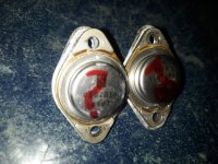
SOLITRON 0602016 8101 is the numbers, and a big "S" i believe is Solitron. RCA?
I been searching for a while now... Hmmmmm..... I would like SPECS and such but its from a 1978 amplifier (AUDIOMOBILE SA-1000)
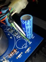
Power source died this time. Uggggg This amp keeps blowing transistors?.... I am guessing thats because of the 45 year old electrolytics...
1 of 3 amps I own, this one keeps having issues. 2 times it was output transistors bad, this time its the power source. Uggggg CAPS?....
Any help will be greatly appreciated ALOHA!
Thanks!!! D
SOLITRON 0602016 8101 is the numbers, and a big "S" i believe is Solitron. RCA?
I been searching for a while now... Hmmmmm..... I would like SPECS and such but its from a 1978 amplifier (AUDIOMOBILE SA-1000)
Power source died this time. Uggggg This amp keeps blowing transistors?.... I am guessing thats because of the 45 year old electrolytics...
1 of 3 amps I own, this one keeps having issues. 2 times it was output transistors bad, this time its the power source. Uggggg CAPS?....
Any help will be greatly appreciated ALOHA!
Thanks!!! D
Add some data, as in:
Old dry electrolytics can make amp sound bad, but by themselves do not blow transistors.
More important: what does it DO?
Is it a power output transistor or part of the step up voltage switcher?
- Try to find some schematic
- User manual
- post amp/board/guts pictures
- speakers you drive
Old dry electrolytics can make amp sound bad, but by themselves do not blow transistors.
More important: what does it DO?
Is it a power output transistor or part of the step up voltage switcher?
Last edited:

Perhaps we can suggest a replacement knowing the operating voltage and the estimated power it delivers to the load. Several years ago l repaired a guitar amp with strange part numbers blowed. Replaced them with TIP35/36 providing the known suppy voltage. The set was blown by accident turning the 110/220V to 110V. The owner was too happy, as he said me that "sound better than original parts". Who knows.
I looked for documents for "Audiomobile" but did not find anything so actually, a photo of the pcb well framed could help, after working by cross-checking through other car amps, we should be able to do something.
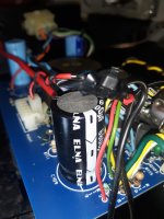
Hi, thanks for chiming in. This is a T0-3 type POWER transistor.... main transistor for the power circuit, theres 2 of them, one is shorted. I might have ran this amp too hard. As the IMPEDANCE goes its currently reads 3.5 ohms at the plug on both speakers and they are quite new Kenwood 6x9 brand. No shorts and I put a different amp in that spot and it ran fine. This amp I ran at 2 ohms for a while in my other car and it thermaled so I pulled it. Recently reinstalled it into my FIREBIRD along with two others I own. Ever since this thing been a PAIN. Popping fuses and blowing transistors, first OUTPUT and now a POWER transistor. Well I found a surplus place that sells them for 22 bucks each. I was hoping to find some specs... schematic etc so maybe I can use a different transistor but as of this writing I am still looking. One of them parts thats been out of production for decades. FUN FUN FUN.Add some data, as in:
- Try to find some schematic
- User manual
- post amp/board/guts pictures
- speakers you drive
Old dry electrolytics can make amp sound bad, but by themselves do not blow transistors.
More important: what does it DO?
Is it a power output transistor or part of the step up voltage switcher?
I think these are 60amp POWER SOURCE transistors and they come from a amp that runs on 12 voltsDC aka automotive stereo amplifier. 0602016 transistorPerhaps we can suggest a replacement knowing the operating voltage and the estimated power it delivers to the load. Several years ago l repaired a guitar amp with strange part numbers blowed. Replaced them with TIP35/36 providing the known suppy voltage. The set was blown by accident turning the 110/220V to 110V. The owner was too happy, as he said me that "sound better than original parts". Who knows.
Greetings Mr Fahey, I been installing autosound in cars since 1973 or so. Never really repaired anything, just installed 12 volt products. In my 60's now... I have a LOT of OLD amps I have collected over the decades and now I want to bring them back to life so I TRY. I read Perry's basic site and learned plenty. Managed to repair several amps thus far. Well this particular amp.... Being a real pain. That being said I am a novice at best in regards to repairs and THEORY etc. So I struggle with the unknown. Thank you for any help you may impart and thanks for that dry cap advice. Good to know. Thank You.Add some data, as in:
- Try to find some schematic
- User manual
- post amp/board/guts pictures
- speakers you drive
Old dry electrolytics can make amp sound bad, but by themselves do not blow transistors.
More important: what does it DO?
Is it a power output transistor or part of the step up voltage switcher?
I will take some pics I suppose... might help. THANKS!I looked for documents for "Audiomobile" but did not find anything so actually, a photo of the pcb well framed could help, after working by cross-checking through other car amps, we should be able to do something.
Thanks 👍 but that is a modern amplifier, sadly many brands recycle old names for marketing reasons.
Yours is 700-1400W , mono, Class D, certainly must use MosFets, at least for step-up switching.
The OP´s one is from the 70´s, 100W+100W Class AB.
@ BIGDOGBRODAVE
Just to avoid confusions, what you call "power" transistor "should" be "switching/power inverter/supply" transistor.
"Output" should be "Output Power Transistor" or something like that.
"Power" by itself may apply to both which is confusing.
Solitron is now defunct (or was absorbed by some other Company) but back in the day (60s, early 70s) they were a big contender, somewhat specializing in high current switching/inverter transistors, including some beefy Germanium ones.
I guess power amplifier must be a somewhat conventional Class AB 100W into 4 ohm amplifier, a staple type way back then (hey! I still make such amps today 😉 ) and sort of repairable by an experiencd Tech even without a schematic, but the switching converter is anybody´s guess; I would HATE to repair it "blind", guess most Techs would think the same 🙁
Maybe you are lucky and replacing stepup inverter transistors is enough ... what if it´s not?
Ok, at least post couple guts pictures, showing inverter and power Amp(s), we might be lucky.
Hi, sorry, These are the main transistors that make the voltage. Power supply. I been lucky. As blind goes, even with a schematic I would be blind. Good to know your limitations. I might get lucky or I might be out some change.......... so far I am out some change on this amp. LOL. Glutton for punishment comes to mind. Thanks for the interest!Thanks 👍 but that is a modern amplifier, sadly many brands recycle old names for marketing reasons.
Yours is 700-1400W , mono, Class D, certainly must use MosFets, at least for step-up switching.
The OP´s one is from the 70´s, 100W+100W Class AB.
@ BIGDOGBRODAVE
Just to avoid confusions, what you call "power" transistor "should" be "switching/power inverter/supply" transistor.
"Output" should be "Output Power Transistor" or something like that.
"Power" by itself may apply to both which is confusing.
Solitron is now defunct (or was absorbed by some other Company) but back in the day (60s, early 70s) they were a big contender, somewhat specializing in high current switching/inverter transistors, including some beefy Germanium ones.
I guess power amplifier must be a somewhat conventional Class AB 100W into 4 ohm amplifier, a staple type way back then (hey! I still make such amps today 😉 ) and sort of repairable by an experiencd Tech even without a schematic, but the switching converter is anybody´s guess; I would HATE to repair it "blind", guess most Techs would think the same 🙁
Maybe you are lucky and replacing stepup inverter transistors is enough ... what if it´s not?
Ok, at least post couple guts pictures, showing inverter and power Amp(s), we might be lucky.
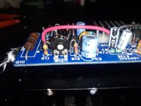
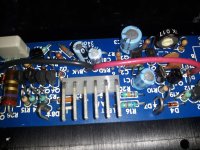
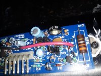
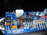
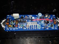
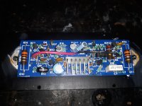
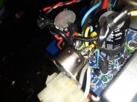
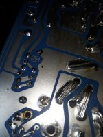
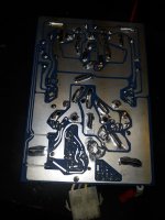
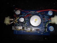
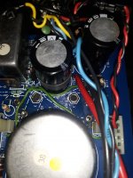
heres some pictures of the SA-1000 Audiomobile amp all apart.
Attachments
-
 20221120_211600.jpg525.8 KB · Views: 178
 -
 20221120_214146.jpg265.5 KB · Views: 173
 -
 20221120_214132.jpg448.1 KB · Views: 145
 -
 20221120_214122.jpg415.9 KB · Views: 138
 -
 20221120_214115.jpg373.6 KB · Views: 131
 -
 20221120_214034.jpg388.6 KB · Views: 144
 -
 20221120_214007.jpg414.4 KB · Views: 147
 -
 20221120_213940.jpg310.5 KB · Views: 147
 -
 20221120_213834.jpg331.5 KB · Views: 132
 -
 20221120_213757.jpg366.8 KB · Views: 129
 -
 20221120_213419.jpg365.8 KB · Views: 146
 -
 20221120_213445.jpg378 KB · Views: 137
 -
 20221120_213516.jpg321.5 KB · Views: 130
 -
 20221120_213544.jpg318.5 KB · Views: 200
 -
 20221120_213607.jpg303.9 KB · Views: 127
 -
 20221120_213644.jpg364.4 KB · Views: 135
 -
 20221120_213720.jpg395.5 KB · Views: 200
I'd just use MJ150024/150025. Too fast? Hopefully, they won't oscillate...
Those aren’t even TO-3. They are even pre-TO-3P. The old TO-218, typical of TIP35/6 or TIP142/147. Depending on whether regular or darlington. Could be either, but the lack of an obvious driver transistor suggests they used darlingtons.
Those TO-3s drive the DC-DC converter (The transformer is in the little can). They will be NPN silicon, capable of a decent amount of current. 15-16 amp audio types need not apply - they will not have enough gain at high current and the self-oscillating converters of the day will drop out of oscillation with those types. Darlingtons have too high a VCE and run really hot so they were never used And this is pre-Mosfet. I successfully made one of these many years ago with 2N5886 switching transistors. The 50 amp version (2N5686) would be a bit better, but has the BIG pins and might not fit your board. Also stupid expensive. The transistors don’t need to be especially high fT. They need to be at least 25 amp types with high gain at high current. If hFE falls to the single digits at 20-25 amps they will be useless when you start extracting any real power out of the supply/amp.
Those TO-3s drive the DC-DC converter (The transformer is in the little can). They will be NPN silicon, capable of a decent amount of current. 15-16 amp audio types need not apply - they will not have enough gain at high current and the self-oscillating converters of the day will drop out of oscillation with those types. Darlingtons have too high a VCE and run really hot so they were never used And this is pre-Mosfet. I successfully made one of these many years ago with 2N5886 switching transistors. The 50 amp version (2N5686) would be a bit better, but has the BIG pins and might not fit your board. Also stupid expensive. The transistors don’t need to be especially high fT. They need to be at least 25 amp types with high gain at high current. If hFE falls to the single digits at 20-25 amps they will be useless when you start extracting any real power out of the supply/amp.
Yes, we have two types of transistors here, doing very different jobs.
Q10/Q11 "NPN-PNP" are the power amp outputs and yes, must be Darlingtons, maybe TIP141/142 as you guessed.
I used them since the late 70´s and they had the "old" TO3P case, designed to not only to replace metallic TO3, they could even use the same mica, everything meant to make it easy for manufacturers to switch types (sales=$$$ 😉 )
Then as they became mainstream, evolved into TO218 > TO247 which often can NOT fit as replacements of the metallic ones because of their square "shoulders".
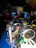
Yes, the TO3 metallic must be the power supply switchers.
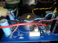
Yes,the grey cylinder marked with "38" and a yellow dot must be a Ferrite pot core.
Looks quite small for the stated 200W RMS amplifier though, specially because way back then, switching frequencies were low , even 20-30kHz or so, because high current Bipolars weren´t fast enough, and that limits power transfer.
I still have somewhere the RCA book "Power Electronics" or something, (1978??) covering designs of such inverters, most self excited.
They even suggested specific Arnold cores, to simplify designer´s jobs.
Oh the good old times when "everything" was made in USA 🙁
Back to the OP problem, the stumbling block is we have NO schematics at all, complicating troubleshooting.
On the other side I see nothing cracked/toasted/smoked so for once, shotgunning might work, meaning blindly replacing power transistors and praying.
What else? 🙁
Q10/Q11 "NPN-PNP" are the power amp outputs and yes, must be Darlingtons, maybe TIP141/142 as you guessed.
I used them since the late 70´s and they had the "old" TO3P case, designed to not only to replace metallic TO3, they could even use the same mica, everything meant to make it easy for manufacturers to switch types (sales=$$$ 😉 )
Then as they became mainstream, evolved into TO218 > TO247 which often can NOT fit as replacements of the metallic ones because of their square "shoulders".
Yes, the TO3 metallic must be the power supply switchers.
Yes,the grey cylinder marked with "38" and a yellow dot must be a Ferrite pot core.
Looks quite small for the stated 200W RMS amplifier though, specially because way back then, switching frequencies were low , even 20-30kHz or so, because high current Bipolars weren´t fast enough, and that limits power transfer.
I still have somewhere the RCA book "Power Electronics" or something, (1978??) covering designs of such inverters, most self excited.
They even suggested specific Arnold cores, to simplify designer´s jobs.
Oh the good old times when "everything" was made in USA 🙁
Back to the OP problem, the stumbling block is we have NO schematics at all, complicating troubleshooting.
On the other side I see nothing cracked/toasted/smoked so for once, shotgunning might work, meaning blindly replacing power transistors and praying.
What else? 🙁
Just try powering it up on a 12 volt 3 to 5A current limited bench supply after fitting new switching transistors. It will either work or shut down the supply.
The inverter could be blown as a result of shorted output trannies in the amp boards. Check those out separately, on a regular plug in power supply, with say an 18-0-18 transformer. And a dim bulb limiter.
The inverter could be blown as a result of shorted output trannies in the amp boards. Check those out separately, on a regular plug in power supply, with say an 18-0-18 transformer. And a dim bulb limiter.
I found some for sale in Nebraska, 60 amp rating NPN type, TRW brand. 22 bucks each plus shipping.... PRE MOSFET.... yes, a 1976 design?. Your input is greatly appreciated. Why it blew... that one. I was "testing" it after I replaced a OUTPUT transistor that shorted, it ran 24 hours at low volume on the bench, reinstall in the car... and now a Power supply transistor fails. My goodness. THANKS!!!!Those aren’t even TO-3. They are even pre-TO-3P. The old TO-218, typical of TIP35/6 or TIP142/147. Depending on whether regular or darlington. Could be either, but the lack of an obvious driver transistor suggests they used darlingtons.
Those TO-3s drive the DC-DC converter (The transformer is in the little can). They will be NPN silicon, capable of a decent amount of current. 15-16 amp audio types need not apply - they will not have enough gain at high current and the self-oscillating converters of the day will drop out of oscillation with those types. Darlingtons have too high a VCE and run really hot so they were never used And this is pre-Mosfet. I successfully made one of these many years ago with 2N5886 switching transistors. The 50 amp version (2N5686) would be a bit better, but has the BIG pins and might not fit your board. Also stupid expensive. The transistors don’t need to be especially high fT. They need to be at least 25 amp types with high gain at high current. If hFE falls to the single digits at 20-25 amps they will be useless when you start extracting any real power out of the supply/amp.
Last edited:
This amp is rated at 50 watts per channel at 4 ohms. OK... pop a couple "new" ones in there and keep my fingers crossed... Been there done that. I have a couple more amplifiers arriving in the mail today so I will go over my CAR, make absolutely SURE theres no ground issues in the speaker wires etc and recheck it all before I install a different amp into that space. I already did a SWAP once and it ran OK. SO I anticipate the new amp I have will operate fine as well. That being said, I would like to get this amp working GOOD. It runs OK at low volumes.... died 3 times now since I ran it hard. I decided to run this amp hard to SEE.... well they not too happy about running hard it appears. The others all run a 4 ohm load and fans keeping em cool, play LOUDLY, clean sounding great amps. THANKS!!!!!!Yes, we have two types of transistors here, doing very different jobs.
Q10/Q11 "NPN-PNP" are the power amp outputs and yes, must be Darlingtons, maybe TIP141/142 as you guessed.
I used them since the late 70´s and they had the "old" TO3P case, designed to not only to replace metallic TO3, they could even use the same mica, everything meant to make it easy for manufacturers to switch types (sales=$$$ 😉 )
Then as they became mainstream, evolved into TO218 > TO247 which often can NOT fit as replacements of the metallic ones because of their square "shoulders".
Yes, the TO3 metallic must be the power supply switchers.
Yes,the grey cylinder marked with "38" and a yellow dot must be a Ferrite pot core.
Looks quite small for the stated 200W RMS amplifier though, specially because way back then, switching frequencies were low , even 20-30kHz or so, because high current Bipolars weren´t fast enough, and that limits power transfer.
I still have somewhere the RCA book "Power Electronics" or something, (1978??) covering designs of such inverters, most self excited.
They even suggested specific Arnold cores, to simplify designer´s jobs.
Oh the good old times when "everything" was made in USA 🙁
Back to the OP problem, the stumbling block is we have NO schematics at all, complicating troubleshooting.
On the other side I see nothing cracked/toasted/smoked so for once, shotgunning might work, meaning blindly replacing power transistors and praying.
What else? 🙁
Last edited:
the amplifier output transistors all checked out fine so on to POWER SOURCE.... It produced a shorted transistor so I started looking for a replacement and wow... So after a day of searching decided to open up to the community here for help. Thank you all for your input.... getting close here. YAY! I will look for anything that dont read right before reinstalling them power source transistors, once i find some. THANKS!!!Just try powering it up on a 12 volt 3 to 5A current limited bench supply after fitting new switching transistors. It will either work or shut down the supply.
The inverter could be blown as a result of shorted output trannies in the amp boards. Check those out separately, on a regular plug in power supply, with say an 18-0-18 transformer. And a dim bulb limiter.
That's what I thought. But no:Solitron is now defunct
https://solitrondevices.com/

Dig the concrete power poles! I know they are common some places, but I had not seen them in the US in recent decades.
They still have transistors:
https://solitrondevices.com/bipolar-transistors/
- Home
- Amplifiers
- Solid State
- SOLITRON T0-3 transistor 0602016 8101