I've been looking at the 2 attached schematics as well as this video outlining something similar:
I'm curious what everyone's thoughts are on a new build with either of these 2 designs. I'm favouring the UTC one as it seems more mature and has fixed bias.
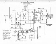
I'd be leaving out some things as well like b+ to preamp, any input capacitors inline with the grids of the first stage, and likely establish bias voltage in a simpler way than is shown using the 6.3v from the filament windings.
I'd likely use all hammond iron for the sake of cost and availability. Something in the 1650 range for the output. I'd likely over-spec everything too in terms of size and current. I'd likely be using KT88's as well since they offer the most power and I have a stash on hand.
Fools errand or shows promise?
I'm curious what everyone's thoughts are on a new build with either of these 2 designs. I'm favouring the UTC one as it seems more mature and has fixed bias.
I'd be leaving out some things as well like b+ to preamp, any input capacitors inline with the grids of the first stage, and likely establish bias voltage in a simpler way than is shown using the 6.3v from the filament windings.
I'd likely use all hammond iron for the sake of cost and availability. Something in the 1650 range for the output. I'd likely over-spec everything too in terms of size and current. I'd likely be using KT88's as well since they offer the most power and I have a stash on hand.
Fools errand or shows promise?
Attachments
What is the conflict that prompts you to ask? What will be the source? Hence what gain do you need?
These are just similar designs I've been interested in and am seeing if there's any red flags or input from the community.
Input drive isn't a problem. Usually I have a DAC with ~2v output
Input drive isn't a problem. Usually I have a DAC with ~2v output

That schematic; the 47K output stage grid leak with the same value in the 6SN7 driver stage anodes is a punitive punishment for the driver stage. Currently, I am also doing a similiar Williamson drive concept, but using 12HG7´s as triodes with 25dB gain in that configuration. Their lower impedance with a vastly reduced anode load will easily drive fixed bias parallel pairs with such low value grid leaks. I am expecting around 150W from a three stage amp using a 6CG7 LTP. More will arrive later. rJI built Williamson long time ago, both LTSpice simulation and prototype, I would suggest you to follow article attached.
The above is the schematic of a very simple EL34/KT66 power amplifier that I modified from the Williamson circuit. The result is really good and I am very impressed with its superb performance.
Not much left of the Wiliamson design there ...
Triode connected output stage, not more.Not much left of the Wiliamson design there ...
Since there is no voltage amplifying stage, the sensitivity is quite low (volts?).
Correct, it´s the intermediate driver stage that is the crux of the problems, when the input and output stages of many amps are nearly all a consistent makeup, thus be branded a "Williamson" is a complete misnomer.Not much left of the Wiliamson design there ...
The design for a good designed diff driver challenge is on. The starting area is now standard; using a CS in the common cathodes with a neg source and cathode to grid feedback can work wonders in excellent balance. This should be encouraged in every design.
I have alot of ex TV frame tubes 12HG7 and sister 12GN7 from my time in early 1970´s as a TV & Audio engineer. (1) tolerances can be wildly out, for video who cared about THD then? (2) selection of many tubes for true audio applications in terms of matched pairs for drivers is an area I have worked on, time consuming burning the midnight oil finding the ideal set makeup in terms of balance of most parameters, took me to testing 200+ tubes, out of which I got 50 pairs of each using a spectrum and distortion analyser. (4) Microphony and non screened, rule out any other sensitive positions in amps. There are advantages (1) using high gm pentodes as triodes but one has to do the math and curves. Straight away there is a 25dB gain in triode config but one has to consider Vg to Cath is markedly lower than other types, so that implies more careful selection. (2) Large area cathodes and long life can be expected in a less harsh operating environment. An output impedance of around 1.5Kohms given a 20mA drive current per tube is a good starting point. Later, I will post some graphs of my findings.
The situation gets tighter when one is looking at matched pairs of both in terms of reasonably equal distortion and harmonics in a diff driver configuration. (3) The input capacitance of these frame tubes is again punitive, again a lowish output impedance of the previous stage LTP is crutial in this aspect to maintain the upper frequency bandwidth. There is no point using an ECC83 with high value anode resistors.
Bear in mind, it is only respectful when Wiliamson insisted on a well designed 18 sectioned output transformer for balance, it is only right that some time be taken over the previous stages in design. I do have two such sectionalised output transformers rated for 150W so, here we go towards a three stage 150W amp. It is achievable.
History; In the early 1970 years I worked TV frames which used enormous quanities of the 12HG7/ 12BY7 group as there was massive competition with the last of the heavy glass wide screens which required more frame drive. These were the last fling variant of TV´s before solid state screens appeared.
More info will come over time.
rJ
- Home
- Amplifiers
- Tubes / Valves
- New 60W Williamson build choices