Help needed…
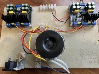
I dug out these two stereo LM1875 boards from my parts bin, looked up the supply spec from the data sheet and have hooked up a twin secondary 15-0-15 80VA supply that I had on hand, I figured this would be good for testing four chips.
These boards utilise a dedicated AC/DC regulation chip KPB307 per LM1875 chip that with along with 2x1000uf 35v CAPS per rail should provide approx 19-20vdc dependant on mains supply by my rough calculation which is within specification of the chip.
As these boards are off the shelf I made assumptions that they would be plug n play. I tested to see if resistors were in spec and soldered properly. One resistor required replacing due to mechanical damage.
So I used a 2amp quick blow resistor and powered up but quickly noticed burning smell, powered it down and have noticed casing of one chip has split.
Have I made a grave error that has caused the damage to the chip or is this likely a failure of a dodgy fake chip?
The chips do not appear to match the genuine case format of lm1875 on data sheet.
I have removed some cables during test so this is not reflective of how it was when powered up as some wires not present in pic.
Attachments
Last edited:
are those 2 black components rectifiers? why 2? single package does the job unless if it uses two separate transformers or a tranny with 2 isolated windings at its o/p . If your tranny is 15-0-15, these 2 bridge rectifiers will result in a short for one half AC cycle. I may be wrong, and these bridge rectifiers may indeed be wired in parallel to supply +/- voltage to each chip as you said
did you use heatsinks on right and removed it for taking photos?
if they are rebadged TDA2030(+/-18V DC max), then such a high voltage will result in chips popping off or possibly fake chips
did you use heatsinks on right and removed it for taking photos?
if they are rebadged TDA2030(+/-18V DC max), then such a high voltage will result in chips popping off or possibly fake chips
Last edited:

There are no discreet diodes the regulation chips mentioned will be a set of diodes in the chip…are those 2 black components diodes?
did you use heatsinks for the regulator on right?
if they are rebadged TDA2030, then such a high voltage will result in chips popping off or possibly fake chips
"dedicated AC/DC regulation chip KPB307".... those are bridge rectifiers.
I would start with only one board.
Are you sure you know how to wire this? Where are those 2 black and one brown wires from top right board connecting to?
The chip without the heatsink is not authentic.
I would start with only one board.
Are you sure you know how to wire this? Where are those 2 black and one brown wires from top right board connecting to?
The chip without the heatsink is not authentic.
I did say in that picture that I had removed some of the wires etc whilst I checked components."dedicated AC/DC regulation chip KPB307".... those are bridge rectifiers.
I would start with only one board.
Are you sure you know how to wire this? Where are those 2 black and one brown wires from top right board connecting to?
The chip without the heatsink is not authentic.
The two black wires and brown are audio input and shield.
Yes the kb307 is a bridge rectifier (which is why no discreet diodes in my other reply). I did this layout like this in order to test one board at a time.
I have built many many products but I do not profess to be an ‘electronics design engineer’ and therefore am hoping to get experienced responses into what I need to test and problem solve this, at the moment I can only assume the chips are fake and the route cause of the issue, what would be great is if anyone has come across these boards and can shed any light on this issue.
Last edited:
Actually, I edited later .There are no discreet diodes the regulation chips mentioned will be a set of diodes in the chip…
Thanks good questions - yes the bridge rectifiers are wired in parallel from what I can see. One section supplying DC to all components for R channel and the rest mirrored for L.are those 2 black components rectifiers? why 2? single package does the job unless if it uses two separate transformers or a tranny with 2 isolated windings at its o/p . If your tranny is 15-0-15, these 2 bridge rectifiers will result in a short for one half AC cycle. I may be wrong, and these bridge rectifiers may indeed be wired in parallel to supply +/- voltage to each chip as you said
did you use heatsinks on right and removed it for taking photos?
if they are rebadged TDA2030(+/-18V DC max), then such a high voltage will result in chips popping off or possibly fake chips
Yes I removed heat sink during analysis - I do think it’s a fake chip and am trying to see from you guys if worth getting some genuine from Mouser to use on these boards.
Thanks for the heads up, before I replace and risk blowing a replacement chip I need to feel confident that the components are all suitable for the supply, I have been unable to find a schematic for these boards so I will just try and sketch one out to share and maybe someone could advise if the values are not suitable?check with @asuslover , I think he has quite a few LM1875 in tubes
No need for an EE degree 😉 so don´t worry about that.
A few doubts/comments:
* plain unshielded wire to feed signal into these amps is a very poor choice.
IF amp oscillates, it may burn a chipamp.
* what are you driving these amps with?
* I suggest you connect and test them one by one
* was any load connected? Speaker/resistive/open output?
* did the chipamp explode just on turn on?
If the latter, those may be very poor fakes, getting guaranteed good ones as suggested above may be worth it.
* just in case, next time you turn them on , go slow:
a) plug power transformer into a lightbulb limiter, suggested lamp wattage 25W or thereabouts
You can still get 15-20W incandescent filament bulbs for sewing machine/fridge use,they usually have a smaller socket, no big deal. You can screw it to that experimental wooden board you show.
b) at least for the first time, start with shorted signal inputs.
Then turn amp on and check all voltages are fine, including 0V dc at speaker out.
Good spot regarding the unshielded inputs, I was not aware that these chips were so sensitive to oscillation, the unshielded run was very short and all connected physically so did not think it could be an issue - I have got some shielded signal wire on order, could oscillation have caused the chip to blow?No need for an EE degree 😉 so don´t worry about that.
A few doubts/comments:
* plain unshielded wire to feed signal into these amps is a very poor choice.
IF amp oscillates, it may burn a chipamp.
* what are you driving these amps with?
* I suggest you connect and test them one by one
* was any load connected? Speaker/resistive/open output?
* did the chipamp explode just on turn on?
If the latter, those may be very poor fakes, getting guaranteed good ones as suggested above may be worth it.
* just in case, next time you turn them on , go slow:
a) plug power transformer into a lightbulb limiter, suggested lamp wattage 25W or thereabouts
You can still get 15-20W incandescent filament bulbs for sewing machine/fridge use,they usually have a smaller socket, no big deal. You can screw it to that experimental wooden board you show.
b) at least for the first time, start with shorted signal inputs.
Then turn amp on and check all voltages are fine, including 0V dc at speaker out.
Welll Cheap Chinese Swill is almost assured to be worthless junk.
Current pricings for a 'real' 1875 chip is likely more than paid for those 'amps.'
Even a 'proper /datasheet' lm 1875 amp is a Decent but hardly an outstanding performer.
Personally I think yer wasting your time.
Current pricings for a 'real' 1875 chip is likely more than paid for those 'amps.'
Even a 'proper /datasheet' lm 1875 amp is a Decent but hardly an outstanding performer.
Personally I think yer wasting your time.
Ok. Still valid input, can you recommend a good solid state build that I could use this transformer with then to better effect.
Ok looks like the advice to take away from this site regarding these boards is don’t bother, thank-you to those who did take the time to respond to my post. I will keep an eye out for some genuine chips and start fresh…
Maybe the boards are fine, but bad chipamps will ruin everything,of course.
My personal experience: I commercially make Guitar Amps, my market is live playing, from Clubs to large venues, so my amps are typically 100W or higher (which is needed to match/beat a drum player), with 60W being borderline for, say, Jazz/Tango/Folkloric music players.
That said, when COVID shut down Live playing for good, my sales crashed, so I decided to make a 25W amp line for home/rehearsal/garage playing.
So I bought 100 TDA2050 from a locally "respected supplier" who "guaranteed" they came straight from ST
A disaster: Chipamps passed a ton of idle current (>>100 ma), overheated, sounded fuzzy, the works with +/-22V supply (standard TDA2050 fare) , yet they were happy with +/-14V rails, typical TDA2030 values.
So not a TOTAL loss, I could "somehow" use them, but only good for 15W RMS into 4 ohm ... not what I need.
The Market is crowded with 15W amps, and I can´t "beat the Chinese" on cost.
"Apparently" some TDA2030 clone or equivalent is available for cents a piece in Asian markets ,which are labelled and sold as if they were the real thing, guess some are labelled "LM1875"
If still interested in the project, I woud buy a couple 1875 from Mouser/Digikey/Farnell only and give it a try.
I think these chips are fake as you say, I cannot see fault in the other components. My background started with guitars and valve amps, I have scratch built them since I was 16, I have since worked in new product development in many industries - aerospace/automotive/military and medical, electronics was never an area I formally studied so always pushed myself to try and figure it out as best I can, I have always known my limits and know when it’s best to seek advice. I will finish this project and curiosity with genuine chips and use the Texas and Brian GT information if the boards appear to throw up more issues, I built an LM3886 based amplifier which has been flawless for about 8 years so was thinking to try the little brother out, my last project utilised class D amplification using the tda3116 which although impressive did not have the dynamics of the LM chips. I was interested to see what the community of minds was like on here to see if it was a good forum to discuss ideas and further knowledge and I thank all those who have put forward positive feedback.Maybe the boards are fine, but bad chipamps will ruin everything,of course.
My personal experience: I commercially make Guitar Amps, my market is live playing, from Clubs to large venues, so my amps are typically 100W or higher (which is needed to match/beat a drum player), with 60W being borderline for, say, Jazz/Tango/Folkloric music players.
That said, when COVID shut down Live playing for good, my sales crashed, so I decided to make a 25W amp line for home/rehearsal/garage playing.
So I bought 100 TDA2050 from a locally "respected supplier" who "guaranteed" they came straight from ST
A disaster: Chipamps passed a ton of idle current (>>100 ma), overheated, sounded fuzzy, the works with +/-22V supply (standard TDA2050 fare) , yet they were happy with +/-14V rails, typical TDA2030 values.
So not a TOTAL loss, I could "somehow" use them, but only good for 15W RMS into 4 ohm ... not what I need.
The Market is crowded with 15W amps, and I can´t "beat the Chinese" on cost.
"Apparently" some TDA2030 clone or equivalent is available for cents a piece in Asian markets ,which are labelled and sold as if they were the real thing, guess some are labelled "LM1875"
If still interested in the project, I woud buy a couple 1875 from Mouser/Digikey/Farnell only and give it a try.
- Home
- Amplifiers
- Chip Amps
- Newbie Help - Testing LM1875 boards