
That's exactly what I was looking at in e-Bay today 😁I think the best heating option for a GU72 UNSET would be an EI transformer with dual chamber bobbin, one per channel. The mosfet should be able to drive pretty much anything but it "feels" right to aim for good insulation and low capacitance.
I´m also interested in trying the UNSET concept some day, but I think I'll start a bit smaller with some tube I'm more familiar with.
A more straight forward GU72 SE prototype would be an interesting winter project though, possibly a btwo stage design using LL1660/10mA interstage transformers.
A more straight forward GU72 SE prototype would be an interesting winter project though, possibly a btwo stage design using LL1660/10mA interstage transformers.
My first attempt will be using EL509/519s, got several of them, and only after that will decide about the GU-72I´m also interested in trying the UNSET concept some day, but I think I'll start a bit smaller with some tube I'm more familiar with.
A more straight forward GU72 SE prototype would be an interesting winter project though, possibly a btwo stage design using LL1660/10mA interstage transformers.
EL509/519 should be a very good choice for an UNSET, as far as I can understand the concept.
I'm beginning to remember that I actually started building a GU72 SET years ago, I should have the half-finished top plate somewhere.
I'm beginning to remember that I actually started building a GU72 SET years ago, I should have the half-finished top plate somewhere.
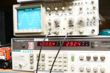
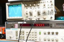
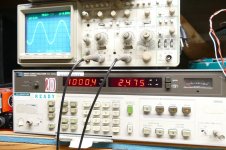
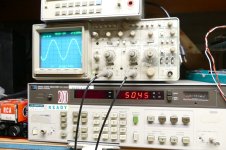
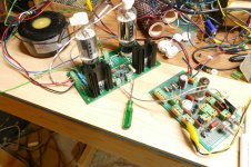
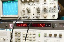
I have been working on a new driver circuit design. The initial breadboard is seen here putting out 50 Volts rms at 0.0792% THD into a 10 K ohm resistor. Once satisfied that I couldn't squeeze any more out of it I connected it up to an UNSET octal output board with both channels wired in parallel through a Toroidy 1.5 K ohm SE OPT. Tubes are 26HU5 TV sweep tubes. Total amp THD is 2.475% at 50.45 watts and clipping starts to show up at 54.44 watts with 2.924% THD. Don't expect that performance below 50 Hz with an OPT that you can hold in one hand. A Hammond 1628SEA miswired for a 2500 ohm load will do a bit over 30 watts at 1 KHz and do it down to about 25 Hz before saturation creeps in.
In some early UNSET experiments, I tried some 307A DH pentodes. As with your tubes you will need a separate heater supply for each tube, or you will be connecting the two channels together. I used a 6.3 volt split bobbin transformer a bridge rectifier, fat cap and appropriate resistor to get the 5.5 volts at 1 amp that the 307A needed. The UNSET mosfet had no problem driving it all. HF response was limited by the 5K ohm Edcor OPT.
In some early UNSET experiments, I tried some 307A DH pentodes. As with your tubes you will need a separate heater supply for each tube, or you will be connecting the two channels together. I used a 6.3 volt split bobbin transformer a bridge rectifier, fat cap and appropriate resistor to get the 5.5 volts at 1 amp that the 307A needed. The UNSET mosfet had no problem driving it all. HF response was limited by the 5K ohm Edcor OPT.
Attachments

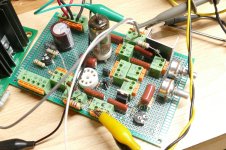
@Tubelab_com, on an un-related question, I noticed in your board photo that you separate the mosfet pins artificially, you do not use the standard footprint. Is that because of the short distance between adjacent pads (0.6mm)? Or just because originally it was designed for a different footprint?
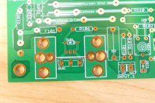
I'm putting together yet another CCS PCB and was wondering about the closeness between the anode and the gate of a 10M45S.

I'm putting together yet another CCS PCB and was wondering about the closeness between the anode and the gate of a 10M45S.
It looks like is a to247 footprint. As far as I can google it, the air dielectric constant is at least 1200V/mm. I am thinking outside the box here but semiconductor manufacturing would not rate devices like 10M90S knowing pins could arc on the pcb.
BUT If there is a guy that has arced to220 pins doing very important experiments for the good of the audio community is probably George!
BUT If there is a guy that has arced to220 pins doing very important experiments for the good of the audio community is probably George!
I noticed in your board photo that you separate the mosfet pins artificially, you do not use the standard footprint.
I laid out the board to accommodate a TO-220 or a TO-247, and to accept several different heat sinks on either side of the chassis including using the chassis itself as a heat sink. There are only so many ways to do this and since it's a lot easier to bend the pins in a TO-220 than a TO-247, the TO-220 gets bent if it uses the big heat sink on the top side. I have some TO-220 mosfets that are rated for 900 volts. 10M90S parts exist and they are in a standard TO-220 package. I have seen some 1200 volt TO-220s. The 1700 volt parts do have an odd offset footprint.It looks like is a to247 footprint.
Attachments
- Home
- Amplifiers
- Tubes / Valves
- Ukrposhta delivers... now I have to something with this!