Subject of this thread is not about sales, market or selection.
Ah, okay then.
Who alredy knows ultra low noise area and application, have measured NJM2122 and want to share results - welcome.
Care to share the PCB design you used... and details about the power supply you used? How did you connect that pot you referred to as a bias compensation measure, i.e. the "nothing fancy" bit of information... How did you wire it?
So, which TL431 manufacturer turned out to have the lowest noise part?Measurements I've done so far, shows that TL431 is not the same if it made by TI, ST or OnSemi. Difference could reach x5 times.
That NJM2122 would be great for my phono front end. The OPA1656 my be perfect for the 2nd stage.
It wouldn't work as a replacement due to its limitations of +/- 10V (DIP). The voltage follower circuit must not be used.
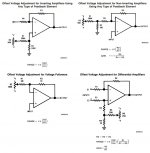
I use protoboard from amazon, 830. I'd put "working material" pictures, it says what this all about. Offset circuits, right, published in the text book , any FPGA programmed robots knows such circuits by heart.Ah, okay then.
Care to share the PCB design you used... and details about the power supply you used? How did you connect that pot you referred to as a bias compensation measure, i.e. the "nothing fancy" bit of information... How did you wire it?
Attachments
-
 Offset.jpg77 KB · Views: 147
 -
 5.lm4040C20.JPG636.2 KB · Views: 136
 -
 7.tl.431-onsemi-11mA.JPG693.1 KB · Views: 100
 -
 9.tl.431-stm-11mA.JPG679 KB · Views: 104
 -
 60dB 15kHz ref5025 a.JPG742 KB · Views: 93
 -
 60dB 15kHz ref6130.JPG414.2 KB · Views: 91
 -
 AP7381-3mA-1.10uF.JPG698.1 KB · Views: 87
 -
 ap.7381 15mA 22.22uF 40dB.JPG795.9 KB · Views: 115
 -
 lm.2950 15mA 22.22uF 40dB.JPG906.7 KB · Views: 113
 -
 mcp1702 15mA 22.22uF 40dB.JPG723.5 KB · Views: 134
The bipolar input opamps will be less immune to RFI because the inputs stages have high gm compared to JFET or CMOS devices like the 1642 and 1656 which are usually very good wrt RFI (thr data sheets show the RFI immunity).I see. My argument is that many applications in the audio domain not necessaraly in the signal 20-20k path. Low noise power suppllies, for example. Or buffering amplification and measurements with circuits that in the signal chain. ADC buffers.
So far I can't get stable noise data with any TI IC. Tryed opa1611 opa1602 - both very sensitive to RF enviroment. LM4562, opa1656, opa1641, opa145 all same problem. Don't llike an idea to design triple shielding box for any simple project I may come up with. NJM is very good in this aspect, perfectly works even on a breadboards.
For best thermal noise, the bipolar devices should be fed from source impedances of <1k ohms. The JFET/CMOS input devices are best suited for Rsource > 1k.
As mentioned by xrk961, decoupling on all the new high GBWP opamps is critical. I use 0805 right at the opamp supply rails. Keep the feedback resistors very close to the inverting pin and capacitance from the inverting pin to 0V low (no ground traces too close).
I don’t think the NJM2122 is a better device than the OPA1612 which has an input noise of 1.1 nV rt/Hz at 1 kHz and is fully specified- what’s the noise current the NJM device? PSRR?
Last edited:
1. Or IC intentionaly made to be more susceptable. Things more complicated in real world, than what theory says. I'm sure all modern semiconductors have a somekind of a traker, PN number or active transmiter for PN sequence . In some cases, this done stupidly wrong, and tracker undermine IC performane.1. The bipolar input opamps will be less immune to RFI because the inputs stages have high gm compared to JFET or CMOS devices like the 1642 and 1656 which are usually very good wrt RFI (thr data sheets show the RFI immunity).
///
2. I don’t think the NJM2122 is a better device than the OPA1612 which has an input noise of 1.1 nV rt/Hz at 1 kHz and is fully specified- what’s the noise current the NJM device? PSRR?
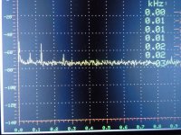
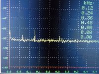
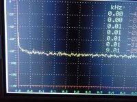
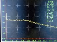
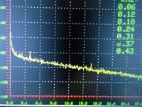
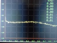
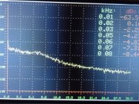
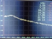
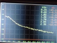
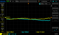
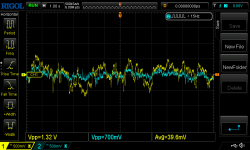
2. I'm not saying what is better or worse. What I say, that I received very good noise data for NJM2122 W/O any extra efforts for decoupling, shielding and woo-doo magic. See OPA1602 vs NJM2122 below, taken in exactly the same conditions - voltage- power suplies, temp, RF enviroment, "side-by-side". I repeated test using alluminium heavy shielding box - makes no difference.
I don't care much what they printed in data sheets, plese stop quiote this BS.
What is get my curiosity, is what WAS NOT printed. Trackers, act of sabottage integrated inside of IC, any abnormality.
Attachments

Well, I don't know, but I think the noise screens you posted do not show low noise.1. Or IC intentionaly made to be more susceptable. Things more complicated in real world, than what theory says. I'm sure all modern semiconductors have a somekind of a traker, PN number or active transmiter for PN sequence . In some cases, this done stupidly wrong, and tracker undermine IC performane.
2. I'm not saying what is better or worse. What I say, that I received very good noise data for NJM2122 W/O any extra efforts for decoupling, shielding and woo-doo magic. See OPA1602 vs NJM2122 below, taken in exactly the same conditions - voltage- power suplies, temp, RF enviroment, "side-by-side". I repeated test using alluminium heavy shielding box - makes no difference.
I don't care much what they printed in data sheets, plese stop quiote this BS.
What is get my curiosity, is what WAS NOT printed. Trackers, act of sabottage integrated inside of IC, any abnormality.
What is the noise level you read from those graphs?
Jan
I had same question. You need to ground the input pins and you should be looking at the 5mV scale or with an FFT noise analyzer. I see huge amounts of noise in those traces. Something is off with the test circuit.
Here's the Amazon 830 protoboard

I don't think this is the way to test any opamp, and especially for noise. If you refuse to read the data sheet and understand the numbers, you will get burned. It's as simple as that.
I don't think this is the way to test any opamp, and especially for noise. If you refuse to read the data sheet and understand the numbers, you will get burned. It's as simple as that.
I agree, a solderless breadboard cannot be used for critical low noise opamp work. At minimum, use P2P soldering on copper plane vero board PCB.
Or do home acid etch - I did this for testing OPA1688. It works great.

I think you can buy breakout boards for SOIC8 chips and install your usual ancillary parts nearby. Like the critical 100nF X7R bypass caps right at the pads for the +/-ve rails.
Or do home acid etch - I did this for testing OPA1688. It works great.
I think you can buy breakout boards for SOIC8 chips and install your usual ancillary parts nearby. Like the critical 100nF X7R bypass caps right at the pads for the +/-ve rails.
Numbers means nothing, most of them "typical" - so no responsibility whatever, just decoration. They put those data to manipulate crowd. I trust only what I see on a screen with my eyes. If TI shows crap, than it belongs to garbage can. Customer is always right, remember?Here's the Amazon 830 protoboard
View attachment 1104362
I don't think this is the way to test any opamp, and especially for noise. If you refuse to read the data sheet and understand the numbers, you will get burned. It's as simple as that.
Noise amplified by 120 dB. But it really doesn't matter, since you just compare LM833 to NJM2122, differemce is obviousWell, I don't know, but I think the noise screens you posted do not show low noise.
What is the noise level you read from those graphs?
Jan
Numbers means nothing, most of them "typical" - so no responsibility whatever, just decoration. They put those data to manipulate crowd. I trust only what I see on a screen with my eyes. If TI shows crap, than it belongs to garbage can. Customer is always right, remember?
A proper test bed (a good PCB layout), and very low power supply rails' noise (which you haven't shared the details of), would allow you to PROPERLY test the OPAmps you so readily discarded.
I suppose you could still say that the rest is garbage because they started to oscillate on that Veroboard of yours that you think is okay to use for testing.
"Customer is always right, remember?" ... except when they are NOT.
You have no analytics skills. Logic behind my desision is dumb simple. If video OPAMP with 200 MHz doesn't oscillate on a breadboard, but some TI IC with GBW barely passing 20 MHz on the same board does oscillate - than internal circuits design of this audio IC was done by idiots.A proper test bed (a good PCB layout), and very low power supply rails' noise (which you haven't shared the details of), would allow you to PROPERLY test the OPAmps you so readily discarded.
I suppose you could still say that the rest is garbage because they started to oscillate on that Veroboard of yours that you think is okay to use for testing.
"Customer is always right, remember?" ... except when they are NOT.
I don't care if such IC would works on properly designed board with 4 layers and heavily decoupled, I would not tolerate that manufacturer would dictate me conditions what I should follow with my hobby grade project. There is always alternative, stop to be "obsessed" by TI.
The video amps are designed to achieve spec sheet performance if implemented properly. You should have more respect for designers - they are certainly not idiots.
I use NJM too - the NJM2068 is a great basic opamp and it works fine for most audio uses. I just like the TI OPA1656 when I need lots of current drive and a FET input. When implemented well, they work without oscillation. Many people here in this forum seem to not have issues with TI products oscillating so perhaps there is an issue with your setup or circuit. We are not all TI “Fanboys” but venting your frustration with ad hominem attacks on the manufacturing design team is not very productive and isn’t making you any friends around here.
Can you tell us what you used to amplify the noise by 120dB and still have low noise? That would be a very interesting piece of equipment!Noise amplified by 120 dB. But it really doesn't matter, since you just compare LM833 to NJM2122, differemce is obvious
Jan
- Home
- Amplifiers
- Solid State
- Low Noise OPAMP NJM2122 is a new shining star