Dear forum,
I'm trying to build a push-pull amplifier and I am struggling to find an acceptable way to wire the 12V to the tube connectors. I've enclosed a schematic representation of the lay-out of my amp. I am afraid the filament wiring will interfere with the input wiring.
I would really appreciate some input on how best to achieve my wiring.
Last edited:
Have you seen the heater wiring thread?
https://www.diyaudio.com/community/threads/heater-wiring-the-good-the-bad-and-the-ugly.211731/unread
https://www.diyaudio.com/community/threads/heater-wiring-the-good-the-bad-and-the-ugly.211731/unread
Yes, I have and I tried wiring it accordingly.
At the moment it is like this but I don't know what to do with the input wiring

At the moment it is like this but I don't know what to do with the input wiring
Id put the input jacks all on the right side then route the filaments in from the left flank and the inputs with low capacitance shielded cable from the right flank. Also I'd install the IEC AC inlet on the far left well away from the inputs. The 12V can still be in the middle I'm assuming thats the power xformer which you want in the center for aesthetic symmetry. But there is no aesthetic reason to have to make your back panel have symmetry, nobody sees it!
Silly question I'm sure, but how are you supplying EL84s, that require 6.3v, with 12v? They must be in pairs, i presume?
In retrospect, that would be best, the problem is, the chassis is already build so I'm stuck with this lay-out. I was hoping someone would say "this is going to work just fine" but no such luck.Id put the input jacks all on the right side then route the filaments in from the left flank and the inputs with low capacitance shielded cable from the right flank. Also I'd install the IEC AC inlet on the far left well away from the inputs. The 12V can still be in the middle I'm assuming thats the power xformer which you want in the center for aesthetic symmetry. But there is no aesthetic reason to have to make your back panel have symmetry, nobody sees it!
View attachment 1102257Silly question I'm sure, but how are you supplying EL84s, that require 6.3v, with 12v? They must be in pairs, i presume?
I should have formulated the question differently : how would you wire the heaters in this lay-out ?
Forgive me if I blather on about the obvious, but those things marked "IN", are those the audio signal inputs?
If so, why are the input tubes all the way at the other end of the chassis, with the output tubes between the input jacks and the input tubes?
Why is the 12V supply coming in at the end of the chassis where the input jacks are located? Why not bring that 12V in at the back, where the tubes are?
Also, is that 12V AC? Or is it DC?
Generally speaking, you want the input wiring to be as short as possible, so the input jacks should be placed close to the input tubes, if at all possible.
The reason you're having trouble figuring out where to place the heater wiring is because the input jacks are way at the other end of the layout from the input tubes. That means no matter what you do, the heater wiring will be running alongside the signal input wiring, which is going to increase the chance of hum pickup by the input wiring.
Maybe if you can move those input jacks to the other side of the chassis, back where the tube sockets are. That way you can leave the 12V entry where it is, and the heater wiring will be located far enough away from the input signal wiring.
Thank you for your reply. Yes, these are the input jacks. I realize I should have put more thought in the lay-out but apart from ditching an expensive chassis I don't see what I can do about it. It is 12V AC. Moving the input jacks . I'll have to put them on top of the chassis )which I find very ugly) or buy a new chassis and do more research on the best lay-out.Forgive me if I blather on about the obvious, but those things marked "IN", are those the audio signal inputs?
If so, why are the input tubes all the way at the other end of the chassis, with the output tubes between the input jacks and the input tubes?
Why is the 12V supply coming in at the end of the chassis where the input jacks are located? Why not bring that 12V in at the back, where the tubes are?
Also, is that 12V AC? Or is it DC?
Generally speaking, you want the input wiring to be as short as possible, so the input jacks should be placed close to the input tubes, if at all possible.
The reason you're having trouble figuring out where to place the heater wiring is because the input jacks are way at the other end of the layout from the input tubes. That means no matter what you do, the heater wiring will be running alongside the signal input wiring, which is going to increase the chance of hum pickup by the input wiring.
Maybe if you can move those input jacks to the other side of the chassis, back where the tube sockets are. That way you can leave the 12V entry where it is, and the heater wiring will be located far enough away from the input signal wiring.
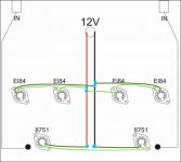
I don't see a layout problem . I would route the wiring like this, twisting pairs snug together everywhere except where needed to be separate right at socket lugs for connection. Run the upper four to its own pair of solder lugs and the 5751 pair to its own. Then right up the centre to supply , all right against the chassis. Pretty simple . . . . . . or am I missing something?
Attachments


I don't see a layout problem . I would route the wiring like this...
I agree, that looks like it should work.
As long as the pairs are twisted tightly, and placed against the chassis, no problem.
Just keep the twisted input wiring high and dry. But move the RCA sockets closer to the board if you can.
There are snap-in hole covers in various colors and materials to cover the original holes.
Just keep the twisted input wiring high and dry. But move the RCA sockets closer to the board if you can.
There are snap-in hole covers in various colors and materials to cover the original holes.
To get this absolutely clear in my mind, this is what you mean ?I don't see a layout problem . I would route the wiring like this, twisting pairs snug together everywhere except where needed to be separate right at socket lugs for connection. Run the upper four to its own pair of solder lugs and the 5751 pair to its own. Then right up the centre to supply , all right against the chassis. Pretty simple . . . . . . or am I missing something?
Last edited:
Well, maybe better in a section on how not to draw a diagram but doing it in an old version of OSX preview it's what we get.
I hope it's clear enough for you to see what is meant. It's not the only possible way but it keeps it clean and simple.
As Rayma mentioned in his post. Pay attention to twisting them well and laying tight against the chassis, then you can get distance with the twisted signal wire pairs by letting them be separate in the vertical plane if you need to. Like 3D checkers sort of image.
Where wiring has to cross, crossing at as near right angles as possible is what is usually recommended. It keeps the area of possible interaction as small as possible and prevents current induction between them.
Attachments
Last edited:
Yes , you're right. That was my error. I was focused on your layout question. I blinked at a small basing diagram, missed the centre-tap, and with the heater voltage for the 8751 written on your layout drawing still in mind was happy to conclude the heater pin-out was 1 and 9 for 6.3V .
The pin-out in my sketch is wrong for the 5751.
Being centre-tapped you can wire them either for 6.3V + 6.3V in series or 12.6 V + 12.6V in parallel. It's up to you .
The pin-out in my sketch is wrong for the 5751.
Being centre-tapped you can wire them either for 6.3V + 6.3V in series or 12.6 V + 12.6V in parallel. It's up to you .
- Home
- Amplifiers
- Tubes / Valves
- Filament wiring question