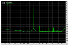
Hmm, I see the third and other odd harmonics only just over 80 dB down and adding the rest of the distortion peaks, I don't think that the THD is anywhere near down to the 86dB or 0.005% as claimed.
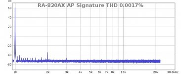
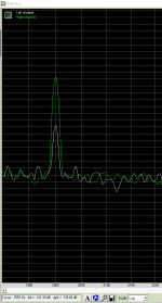
I enclose a RTA plot of one of my recent AP Signature amps (with absolutely no mods to the power supply lines or bias capacitor) measuring 0.0017% THD.
It is absolutely possible to get these improvements with only a few direct drop-in upgrades.
Per
I enclose a RTA plot of one of my recent AP Signature amps (with absolutely no mods to the power supply lines or bias capacitor) measuring 0.0017% THD.
It is absolutely possible to get these improvements with only a few direct drop-in upgrades.
Per
Attachments
According to the attached graph (-3dB), the third harmonic does not exceed -86dB, which terms of 0.005%. I don't remember the exact details. This is better than the manufacturer's stated 0.03%, -70dB.
Measurements do not always reflect the character of the amplifier's sound.
Measurements do not always reflect the character of the amplifier's sound.
Last edited:
What was used to measure 0.0017% - 95 dB THD? ASUS Xonar U7 (line-out - line-in).I enclose a RTA plot of one of my recent AP Signature amps (with absolutely no mods to the power supply lines or bias capacitor) measuring 0.0017% THD.
Attachments
Last edited:
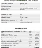
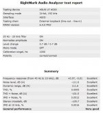
I must admit that I have never seen that Russian(?) report on an ASUS U7 before - and maybe that is not surprising, as it is dated 00:45 - this morning!
Even so, the results seem very strange. I have never seen distortion peaks of 26dB above the noise floor in a U7 loop-back test.
It has been a few years since I did them and the files now sit somewhere on an old hard drive, but there are at least some indications in post #64.
It is also strange that the U7 should have internal 50Hz peaks - when it is powered by +5V USB?
This indicates to me that there must be a serious flaw either in the U7 device measured, the RTA instrument - or the loop setup.
I use a the U7 Mk2 (I think), but I have never heard of the RightMark Audio analyzer. I think that this may well be the 'fly in the ointment' - which could also explain the distortion peaks on the RTA trace you shared in #741 above.
A 'quick and dirty' estimate of the THD in that trace provided it to probably be somewhere just under 0.010% - that is if the analyzer is to be trusted.
Finally, YES I would absolutely love😍 to own a proper Audio Precision box, but my bank manager disagrees.😞
Per

I must admit that I have never seen that Russian(?) report on an ASUS U7
http://personalaudio.ru/detail/asus_xonar_u7/
ASUS Xonar U7 MKII
https://ru.gecid.com/mmedia/asus_xonar_u7_mkii/?s=all
I use a the U7 Mk2 (I think), but I have never heard of the RightMark Audio analyzer.
RMAA is very worthy, apparently different card instances.
https://www.diyaudio.com/community/...c-and-measurements.330472/page-4#post-5737957
#741 was not measured by Asus. TASCAM US-2x2 or US-4x4 I don't remember exactly.
Last edited:
Finally, YES I would absolutely love😍 to own a proper Audio Precision box, but my bank manager disagrees.😞
I found some improvements on the Internet, I think you can try.
Attachments
Hi Sam,
That is interesting, I have been looking for the U7 schematic for some time. Could you share the link please?
Per
That is interesting, I have been looking for the U7 schematic for some time. Could you share the link please?
Per
Hi Per,
https://forum.ixbt.com/topic.cgi?id=12:54737:996#996
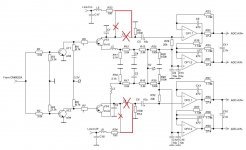
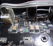
The main problems of the ADC and the power supply of the 5V op-amp, gidagap also turned off the transistor switches.
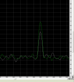
I found the Xonar U7 MKII, measured it, but the miracle did not happen.
https://forum.ixbt.com/topic.cgi?id=12:54737:996#996
The main problems of the ADC and the power supply of the 5V op-amp, gidagap also turned off the transistor switches.
I found the Xonar U7 MKII, measured it, but the miracle did not happen.
Attachments
Last edited:
Hi Sam,
I am afraid that my Russian is a bit Cyrillic, I had hoped you had a link to the full schematic of the U7?
I am afraid that my Russian is a bit Cyrillic, I had hoped you had a link to the full schematic of the U7?
Hi Per,
I couldn't find a complete diagram on the internet.
I think that at 5 volts it is difficult to achieve significant improvements,
even with op amps with rail input and output. After all, the 2 volts rms required for improvements is almost 6 volts peak-to-peak.
Perhaps I'll try to install the OPA2156 rail-to-rail operational amplifiers (op amps) type.
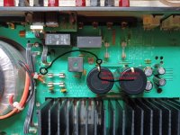
That said, you are right about the high currents inthe power supply. This is particularly true in the ground star connections and I always add a strip of copper braid between the ground potential terminals and the black return wire to the transformer, see pic 1. It could perhaps be argued that the trafo wires could be thicker, but there is not much we can do about that.
Per
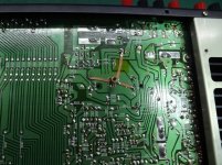
Hello, I would like to understand it precisly, as I work with RA-01, RA-02 and RA980BX so far. They do not have "one grounding point: as RA930/931. By this you are connecting "ground" of the main filtering caps (in RA01, 2x6800 uF) with thicker copper wire, right? And this connected "ground" you are connecting by thick copper wire" with Ground of the trafo, right? I showed it in the picture with black line.
Attachments
HI Piotrek,
Yes, I use a piece copper of solder wick in the 930/930 (and two in the RA-820AX). The RA-980BX has got a massive central ground plane, so it may not need further help - and the RA-01/02 appears to use the advantage of a more modern, more clever pcb layout software and in my experience they do not seem to show these grounding issues as much. But they all do have a central ground point, either a pcb Faston or tab which is screw connected to the bottom panel.
In the RA-01/02 you could try to fatten the pcb track between this tab and the black wire to the transformer and see if there is any 50/100Hz reduction.
I don't recall that I have ever done that.
Best,
Per
Attachments
Hi AngelP,
I'm happy that i found your thread here on diyaudio. I own an Rotel RB-990BX and I am curious how to improve the sound quality of it. I read the books of Self and Cordell. So I'm planning to convert the Amp from shunt compensation to Miller compensation and reducing the VAS loading. I got only mixed results in Simulation regarding stability. Now I saw how you tuned similar amps here in your thread. I'm wondering that you left in the shunt compensation capacitor and added Miller compensation to it. Is there a particular reason for this? Stability?
This tread is realy inspiring to me. Thanks for sharing your thoughts on Rotel Amps!
Cheers,
Sebastian
Привет Пер,полная схема U7?
BoardViewer
Attachments
Hi Sebastian,
Thank you for the kind words.
No, I do not leave in either of the 'Rotel standard' 33k or the 330pF shunts (or heavy lag loads). But I do put in a small 27 or 33pF instead as extra safety against possible output stage HF instability, although I admit that I don't know how it exactly works.
I seem to remember that Self describes its suggested function as 'empirical' - anyway, it does no harm whatsoever.
Best,
Per
Hi Sam,
I seem to have problems in opening the zipped ASUS document. But I will try another zip program.
Best,
Пер 😉
I seem to have problems in opening the zipped ASUS document. But I will try another zip program.
Best,
Пер 😉
BoardViewer.exeI seem to have problems in opening the zipped ASUS document. But I will try another zip program.
Removing the transistor switch in the left channel reduced the second harmonic. I continue the experiment.
Attachments
Hi Per,Hi Sebastian,
Thank you for the kind words.
No, I do not leave in either of the 'Rotel standard' 33k or the 330pF shunts (or heavy lag loads). But I do put in a small 27 or 33pF instead as extra safety against possible output stage HF instability, although I admit that I don't know how it exactly works.
I seem to remember that Self describes its suggested function as 'empirical' - anyway, it does no harm whatsoever.
Best,
Per
I refer to the cap between the VAS transistors collector and supply rail. I would call this cap the shunt compensation. This cap will do the main part of phase correction in an Rotel stock setup. I am just wondering why you left these in the circuit at your mods.
Best,
Sebastian
Ah, those. They are (I believe) mainly for HF stability of the output stage.
I have tried to take them out, leave them in - or reducing their values. No difference either in distortion, slew rate - or sound (much unlike removing the Rotel VAS load pair to ground).
Stability-wise, well I haven't tested the full imaginative range of speaker loads (electrostatics, etc.), but I haven't seen any differences in stability on any of the basic tests that I have done - with or without these caps.
And, being the lazy b*gger that I am, mostly I just leave them be.😉
But as always, I would definitely welcome any knowledgeable input or in-depth explanation on this - you are never too old to learn new stuff.
Best,
Per
- Home
- Amplifiers
- Solid State
- Improve a Rotel amp THD by 20dB!