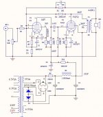
I purchased an assembled 6AU6 6AQ5 SE Amp from China. It worked as assembled but was not correct. The PCB was not correct. I had to cut traces, add correct capacitors/resistors for the voltages and rewire correctly the power supply CRC filters. I have questions about the feedback connections circled in red in the attached picture. I have not seen this before having feedback connected to Pin 2 the suppressor of 6AU6. And I have not seen the R2 240k resistor feedback connected to the suppressor before, but to Pin 5 the plate. Are these connections correct or is this an error too? Or if correct how does this affect the circuit? >>>I have corrected schematic to show 5Y3GT and the added 10uf 400V Capacitor. ALSO Attaching Original Schematic<<<


Attachments

Last edited:
C3 is odd feedback too. I haven’t seen that done before. The 6AQ5 like a 6v6 with slightly lower voltages and it shows the pin 6 voltage is higher than pin 5, shouldn’t it be lower?
Yes, the 6au6 circuit is defiantly odd to me. Yes, the 6AQ5 pin 6 is slightly high (4V) a lot better than the 283V it had on it when I received it. When I calculated the resistor, I actually put a larger resistor in than calculated, but real world still was higher than calculated. I think actual tube screen current is different now. So will have to but a larger screen resistor in. I have operated 6AQ5s in other amps at 300V on plate and screen with no issue. Just adjusting this amp to spec's. Like I stated the amp worked as delivered although with mistakes and errors. I am also searching online for more info on this 6AU6 scheme this amp using.C3 is odd feedback too. I haven’t seen that done before. The 6AQ5 like a 6v6 with slightly lower voltages and it shows the pin 6 voltage is higher than pin 5, shouldn’t it be lower?
Looks to me like an attempt to apply feedback from output plate (and OPT's output) to driver cathode, while keeping the surpressor grid at a negative voltage WRT the cathode?
OK, what is the benefit of doing this?Looks to me like an attempt to apply feedback from output plate (and OPT's output) to driver cathode, while keeping the surpressor grid at a negative voltage WRT the cathode?
A good question. I can't tell if it's clever or stupid. Feedback from output plate to driver cathode has been quite common for the last 70 years or so, nothing particulary special there. Mixing it with feedback from the output transformer should also work as long as the phase relationships are correct. Re. the surpressor grid bias it's something I've seen here and there but never really looked into.
Thanks for response. I have been searching online most of the afternoon and have found nothing like this scheme. All I have found so far are suppressor to cathode pin 7 or to ground. Still researching.A good question. I can't tell if it's clever or stupid. Feedback from output plate to driver cathode has been quite common for the last 70 years or so, nothing particulary special there. Mixing it with feedback from the output transformer should also work as long as the phase relationships are correct. Re. the surpressor grid bias it's something I've seen here and there but never really looked into.
The suppressor G3 has little effect as long as it is much lower than G2 and not swinging a lot. I can't say I ever saw it done that way but I doubt it makes much difference.
Thanks for response. I am thinking about cutting trace to pin 2 suppressor and wiring pin 2 directly to pin 7 cathode. Then cutting trace from R2 240k and wiring to pin 5 of 6au6 plate as I have seen in other schemes. See any issues to this idea?The suppressor G3 has little effect as long as it is much lower than G2 and not swinging a lot. I can't say I ever saw it done that way but I doubt it makes much difference.
I found the original schematic of the amp you posted:
http://www.tube-amps.net/EA_Hashimoto_6AQ5W_6005_SE_4ch.htm
http://www.tube-amps.net/images/6AQ5W_4Ch/6AQ5W_Schematic.jpg
It also indicated the level of gNFB (15.5db) in used, not mentioned in China sch so worthwhile to note.
http://www.tube-amps.net/EA_Hashimoto_6AQ5W_6005_SE_4ch.htm
http://www.tube-amps.net/images/6AQ5W_4Ch/6AQ5W_Schematic.jpg
It also indicated the level of gNFB (15.5db) in used, not mentioned in China sch so worthwhile to note.
Last edited:
Fantastic! Thank YOU! Better than I was expecting. Good to know not a mistake. But does show another China error though with the wrong size plate resistor. I was wondering why the plate voltage was higher for me than the schematic showed. 204v vs 142VI found the original schematic of the amp you posted:
http://www.tube-amps.net/EA_Hashimoto_6AQ5W_6005_SE_4ch.htm
http://www.tube-amps.net/images/6AQ5W_4Ch/6AQ5W_Schematic.jpg
It also indicated the level of gNFB (15.5db) in used, not mentioned in China sch so worthwhile to note.
Look at it this way . . .
The suppressor grid is at the same signal voltage as the cathode (notice the negative feedback signals go to the cathode bypass capacitor).
So the suppressor grid gets the same negative feedback voltage as the cathode (from both the output secondary, and the output tube plate).
Often, in other input pentode circuits, the cathode is self biased, with a bypass capacitor across the cathode self bias resistor, and that self bias RC network is connected directly to ground.
And, then the suppressor grid is either tied to ground, or directly to the cathode. Both the cathode and suppressor are at AC signal ground.
The suppressor is either at the same DC as the cathode, or lower DC by the amount of the self bias voltage.
Very common circuit, Yes?
Now, just modify the circuit to have a 2nd resistor as the return resistor to ground from the cathode self bias RC network.
Then, apply the negative feedback to the junction of the 2nd resistor and the self bias network.
By using the negative feedback to the cathode, instead of the driver plate, then the input pentode plate sees a high impedance of the driver plate resistor in parallel with the output tube g1 grid resistor to ground. Non-Schade negative feedback.
Schade feedback from output tube plate to input tube plate loads the input tube plate with a low impedance.
I’m not clear on what changes you made to the power supply, but please confirm what rectifier tube you have. Your schematic (top) shows 5V3, bottom 5z3p, but either seems to be overkill and probably an error (both draw over 3 amps heater current). More likely a 5y3 or 5V4; in that case you should consider reducing the input capacitor (first one after the rectifier). 5y3 needs an input capacitance of <= 20 mF. The original Japanese design used SS diodes, which could cope with higher input capacitances.
Last edited:
Thank you for your response.Look at it this way . . .
The suppressor grid is at the same signal voltage as the cathode (notice the negative feedback signals go to the cathode bypass capacitor).
So the suppressor grid gets the same negative feedback voltage as the cathode (from both the output secondary, and the output tube plate).
Often, in other input pentode circuits, the cathode is self biased, with a bypass capacitor across the cathode self bias resistor, and that self bias RC network is connected directly to ground.
And, then the suppressor grid is either tied to ground, or directly to the cathode. Both the cathode and suppressor are at AC signal ground.
The suppressor is either at the same DC as the cathode, or lower DC by the amount of the self bias voltage.
Very common circuit, Yes?
Now, just modify the circuit to have a 2nd resistor as the return resistor to ground from the cathode self bias RC network.
Then, apply the negative feedback to the junction of the 2nd resistor and the self bias network.
By using the negative feedback to the cathode, instead of the driver plate, then the input pentode plate sees a high impedance of the driver plate resistor in parallel with the output tube g1 grid resistor to ground. Non-Schade negative feedback.
Schade feedback from output tube plate to input tube plate loads the input tube plate with a low impedance.
I have a 5Y3GT installed. And yes, I already installed a 10uf 400V on Pin 8 of rectifier. See picture in post 1. Thanks for your response.I’m not clear on what changes you made to the power supply, but please confirm what rectifier tube you have. Your schematic (top) shows 5V3, bottom 5z3p, but either seems to be overkill and probably an error (both draw over 3 amps heater current). More likely a 5y3 or 5V4; in that case you should consider reducing the input capacitor (first one after the rectifier). 5y3 needs an input capacitance of <= 20 mF. The original Japanese design used SS diodes, which could cope with higher input capacitances.
6A3sUMMER,Yeah, this is an excellent circuit, and very modern thinking. The only improvement I could see possible would be to include smoking-amp's proposed AP patent small additional positive feedback to cancel OPT resistance. Otherwise, excellent as is.
All good fortune,
Chris
All good fortune,
Chris
Thanks for your response.6A3sUMMER,Yeah, this is an excellent circuit, and very modern thinking. The only improvement I could see possible would be to include smoking-amp's proposed AP patent small additional positive feedback to cancel OPT resistance. Otherwise, excellent as is.
All good fortune,
Chris
Good morning, could you explain what smoking-amp's mod is, and an example. Thanks6A3sUMMER,Yeah, this is an excellent circuit, and very modern thinking. The only improvement I could see possible would be to include smoking-amp's proposed AP patent small additional positive feedback to cancel OPT resistance. Otherwise, excellent as is.
All good fortune,
Chris
Quoting smoking-amp: "Far simpler (for linearizing an OT) is an old Audio Precision patent (# 4614914) that effectively removes winding resistance from the OT primary by positive current FDBK. Using Negative resistance equal to the winding resistance. No voltage drop occurs in the OT signal transfer then, but the output tubes do need a small amount of extra headroom to provide the correction current."
https://www.diyaudio.com/community/threads/a-way-to-help-core-saturation-in-se.390419/page-2 post #29
All good fortune,
Chris
https://www.diyaudio.com/community/threads/a-way-to-help-core-saturation-in-se.390419/page-2 post #29
All good fortune,
Chris
I don't think that has any significance at all, just a convenient tye point.I have questions about the feedback connections circled in red in the attached picture.
Some TV horizontal tubes used odd biasing to G3 to prevent the socalled 'snivets'.
Hanging 100 micro F on the 5V3 rectifier is somewhat gross.
Other than the extra Schade FB hookup the cct is otherwise 'oh-Hum'.
Build the beast, hookup as shewn & compare with that to G3 in the regular hookup.
With test equipment, check if any difference at all.😀
Attachments
- Home
- Amplifiers
- Tubes / Valves
- 6AU6 6AQ5 SE Amp Questions