Hi!
I'm designing a PCB using PGA2311 IC. It takes a line level signal and can attenuate (up to 95dB) or amplify (up to 31dB) the signal. Source impedance is specified to be <600 Ohms, and with regard to output impedance it has the "capability to drive 660-Ω loads directly without buffering".
So - I initially drew my PCB with relatively fat traces (1.0mm) for input and output audio, just because I have the space. I recognise that the trace length needs to be as short as possible, so the audio switching and PGA are located close together and close to the edge of the PCB.

My question is - is it better in any respect (immunity to noise??) to use a narrower PCB trace for these high impedance audio lines? What is the 'right' thing to do? I really want to get this right so I would value any constructive feedback!
Thanks!
Pops
I'm designing a PCB using PGA2311 IC. It takes a line level signal and can attenuate (up to 95dB) or amplify (up to 31dB) the signal. Source impedance is specified to be <600 Ohms, and with regard to output impedance it has the "capability to drive 660-Ω loads directly without buffering".
So - I initially drew my PCB with relatively fat traces (1.0mm) for input and output audio, just because I have the space. I recognise that the trace length needs to be as short as possible, so the audio switching and PGA are located close together and close to the edge of the PCB.
My question is - is it better in any respect (immunity to noise??) to use a narrower PCB trace for these high impedance audio lines? What is the 'right' thing to do? I really want to get this right so I would value any constructive feedback!
Thanks!
Pops
Looks like you have the SDI lines separated from the audio, except for the input selects. What are U4 - U7 ?? PCB trace impedances max out about 50 Ohms but it doesn't matter for audio, except you need to avoid capacitance to other signals, especially digital. For low-speed signals, large traces are more robust and mechanically reliable. Do you need a buffer in front of the PGA2311 because the data sheet saz it needs < 2K driver? What are you using for a controller?
The PCB traces in an audio preamp hardly carry any current, so they can likely be the minimum trace width your PCB manufacturer offers. That's typically around 5-6 mil (0.13-0.15 mm) for a low-to-mid quality manufacturer. You can pay extra to get skinnier traces. So that's the lower limit. Similarly, your PCB manufacturer probably offers at least 8-mil (0.2 mm) spacing, maybe tighter. Certainly tighter spacing at an additional cost.
So you could design the PCB with 0.2 mil wide traces spaced 0.2 mm apart. But just because you could does not mean you should. In fact, there are many reasons you should not design a PCB to the manufacturer's minimum specs. The primary ones being manufacturability and yield. Of course, if you only need one board you don't care about yield, but you do care about manufacturability, especially if you don't pay for electrical testing of the PCB after manufacturing. It is very frustrating to spend quality time building a board and even more time debugging it only to discover that the PCB itself has a manufacturing defect. So I highly recommend staying well away from the manufacturer's minimum specs in all but the very tightest areas of the board. With a leaded (or PTH) board there's no reason to be even remotely close to the minimum trace/space.
The same applies to hole sizes. Sure. You can use the minimum hole size, but it will be more difficult to manufacture than a larger hole, so why would you?
For PTH boards I find that 12-mil traces (0.3 mm) on a 25-mil grid (0.64 mm) works very well. That gives me 12/12 mil trace/space. I usually don't go smaller than 20 mil (0.5 mm) diameter holes unless I'm dealing with part that have a very fine pin pitch or for thermal vias. Any PCB manufacturer should be able to make such boards reliably all day. (And yet, it was one such board that came back from my prototype manufacturer with a manufacturing defect).
Back when I was etching my own boards I would use 20-mil (0.5 mm) traces and 20-mil (0.5 mm) space, except in tight areas where I'd drop to 15/15 trace/space (0.38/0.38 mm).
Another trick I employ is that I avoid acid traps. I've marked a couple of them in your layout. Acid traps form at acute angles and can result in over-etching of the traces. This is mostly an issue if you're etching your own boards. It's been a solved problem in the industry for a while (probably decades by now). But still... Why push the process unless you have to?
Tom
Attachments
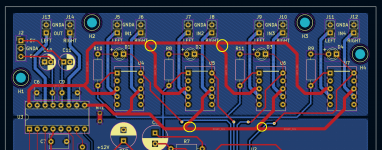

Hi Steve! Thanks for your reply.Looks like you have the SDI lines separated from the audio, except for the input selects. What are U4 - U7 ?? PCB trace impedances max out about 50 Ohms but it doesn't matter for audio, except you need to avoid capacitance to other signals, especially digital. For low-speed signals, large traces are more robust and mechanically reliable. Do you need a buffer in front of the PGA2311 because the data sheet saz it needs < 2K driver? What are you using for a controller?
U4-U7 are signal relays, operated one-at-a-time by a low side driver connected to the top-right pin.
I will try to separate audio from other signals - not possible entirely around the relay itself but I can work on the crossings.
I don't think I need a buffer. I intend using various analogue sources, mainly DA24QS-K (100 Ohm output impedance) and an HRT music streamer III (50 Ohms output impedance). Even my laptop headphone output is likely <50 Ohms output impedance. The PGA2311 datasheet says 'A source impedance of 600 Ω or less is recommended. Source impedances up to 2 kΩ cause minimal degradation of THD+N'. I have built a prototype without any additional buffer and it sounds great. I'm controlling the PGA2311 with a PICAXE 28X2.
So is there any disadvantage in reducing the 1mm audio trace width? Narrower traces, even 0.25mm, add no significant resistance.
One observation - the Right In track is going on the Digital side of the board.
try to use the relays where there is a gap between the signal pins and the NC / NO pin of the relay.
try to use the relays where there is a gap between the signal pins and the NC / NO pin of the relay.
No "sonic" differences unless grossly misdesigned.
If you are passing significant current,that indicates how much copper is needed ; if only signal, ease of fabrication rules.
Personally I try to use 30 or 40 Mil tracks (that´s 1mm or 0,75 mm wide) unless extremely short of space, nothing to win if needlessly going too narrow.
If you are passing significant current,that indicates how much copper is needed ; if only signal, ease of fabrication rules.
Personally I try to use 30 or 40 Mil tracks (that´s 1mm or 0,75 mm wide) unless extremely short of space, nothing to win if needlessly going too narrow.
Thanks Tom,The PCB traces in an audio preamp hardly carry any current, so they can likely be the minimum trace width your PCB manufacturer offers. That's typically around 5-6 mil (0.13-0.15 mm) for a low-to-mid quality manufacturer. You can pay extra to get skinnier traces. So that's the lower limit. Similarly, your PCB manufacturer probably offers at least 8-mil (0.2 mm) spacing, maybe tighter. Certainly tighter spacing at an additional cost.
So you could design the PCB with 0.2 mil wide traces spaced 0.2 mm apart. But just because you could does not mean you should. In fact, there are many reasons you should not design a PCB to the manufacturer's minimum specs. The primary ones being manufacturability and yield. Of course, if you only need one board you don't care about yield, but you do care about manufacturability, especially if you don't pay for electrical testing of the PCB after manufacturing. It is very frustrating to spend quality time building a board and even more time debugging it only to discover that the PCB itself has a manufacturing defect. So I highly recommend staying well away from the manufacturer's minimum specs in all but the very tightest areas of the board. With a leaded (or PTH) board there's no reason to be even remotely close to the minimum trace/space.
The same applies to hole sizes. Sure. You can use the minimum hole size, but it will be more difficult to manufacture than a larger hole, so why would you?
For PTH boards I find that 12-mil traces (0.3 mm) on a 25-mil grid (0.64 mm) works very well. That gives me 12/12 mil trace/space. I usually don't go smaller than 20 mil (0.5 mm) diameter holes unless I'm dealing with part that have a very fine pin pitch or for thermal vias. Any PCB manufacturer should be able to make such boards reliably all day. (And yet, it was one such board that came back from my prototype manufacturer with a manufacturing defect).
Back when I was etching my own boards I would use 20-mil (0.5 mm) traces and 20-mil (0.5 mm) space, except in tight areas where I'd drop to 15/15 trace/space (0.38/0.38 mm).
Another trick I employ is that I avoid acid traps. I've marked a couple of them in your layout. Acid traps form at acute angles and can result in over-etching of the traces. This is mostly an issue if you're etching your own boards. It's been a solved problem in the industry for a while (probably decades by now). But still... Why push the process unless you have to?
Tom
Helpful feedback on the acid traps. I can easily reduce the length of the 45deg traces, and make it closer to an orthogonal junction.
I fully agree on minimum specs - I am currently using 0.25mm traces for very low current signals and circuits, and 0.5mm for power supply (max 50 mA). I think my vias are 1.0mm w. 0.6mm holes, not likely to be challenging.
Based on what you have said there's no reason why I cannot reduce the audio input & output lines to 0.25mm also. That will help with routing and leave more of the ground-plane intact.
Since this Thread is on the PGA2311,
Maybe someone could help me out -
Can I have a little delay of around 2 seconds between the Analog Supply and the Digital supply for the PGA2311,
As for the data, it has been managed to wait for 2 seconds before it sends the last state value after powering up
It's my fault totally because for some reason I bought a 300VA transformer and now I realize that we need to use a SoftStart for it.
my Toroid is 0-24 + 0-24 both at 6amps - this is powering the LM3886 My Ref Rev A (Stereo)
0-12 + 0-12 both at 500mAmps - This was for the analog supply of the PGA2311.
Thanks - I will fix this. I will keep the analogue audio traces above the analogue audio ground plane.One observation - the Right In track is going on the Digital side of the board.
try to use the relays where there is a gap between the signal pins and the NC / NO pin of the relay.
Hmm not sure. I have destroyed a PGA2311 by working with only digital power connected (no analogue power). It's a known limitation (now known also to me). 2 seconds might be ok.Since this Thread is on the PGA2311,
Maybe someone could help me out -
Can I have a little delay of around 2 seconds between the Analog Supply and the Digital supply for the PGA2311,
As for the data, it has been managed to wait for 2 seconds before it sends the last state value after powering up
It's my fault totally because for some reason I bought a 300VA transformer and now I realize that we need to use a SoftStart for it.
my Toroid is 0-24 + 0-24 both at 6amps - this is powering the LM3886 My Ref Rev A (Stereo)
0-12 + 0-12 both at 500mAmps - This was for the analog supply of the PGA2311.
I guess that it's better to get a transformer with all 3 supplies - Amp, Analog for PGA, and Digital supply for the PGA so in my case the timing issue will not be there.Hmm not sure. I have destroyed a PGA2311 by working with only digital power connected (no analogue power). It's a known limitation (now known also to me). 2 seconds might be ok.
I'll try that. I might also delete the indicator LEDs. Not worth compromising the layout for them.Can you rotate all four of the relays 90 degrees clockwise?
What about two transformers, one for the high-power amplifier and another ~9V AC for the 5 volt circuitry? Then use a P05D from ESP to regulate the 9VAC down to +/-5V DC for the PGA analogue supply. I'm using a separate (simpler) ESP regulator for the digital supply, running off the same 9V AC source. Because I'm lazy and I like to keep the transformer outside of the box, I'm using a 230V/9V AC/AC transformer. I appreciate this doesn't give you anything to power your LM3886.I guess that it's better to get a transformer with all 3 supplies - Amp, Analog for PGA, and Digital supply for the PGA so in my case the timing issue will not be there.
You can keep led but use SMD ones on the top Layer, maybe 0805 size. Depends on how comfortable you are.I'll try that. I might also delete the indicator LEDs. Not worth compromising the layout for them.
Or you can keep them on the cpu side of you are driving the relays via a uln2003/4 chip
I bought a 300VA transformer and now I realize that we need to use a SoftStart for it.
You don't need a soft start for a 300VA transformer, not even a thermistor.
Why not just put all the supplies on the soft start? Then they'd come up at the same time.Can I have a little delay of around 2 seconds between the Analog Supply and the Digital supply for the PGA2311,
As for the data, it has been managed to wait for 2 seconds before it sends the last state value after powering up
It's my fault totally because for some reason I bought a 300VA transformer and now I realize that we need to use a SoftStart for it.
I'm not intimately familiar with the PGA2311, but I am familiar with IC design. If you bring up one power supply but not the others, you run the risk of turning something on through the ESD protection devices on the chip. That's usually not a recipe for anything good. I've seen cases where chips have latched up and pulled very high supply current if one supply was significantly delayed.
To know for sure I suggest asking on TI's E2E forum. They're pretty fast to respond usually.
Tom
Depends on how long you want that transformer to live and how oversized you're willing to make the mains fuse. 200-300 VA is usually where I start recommending a soft start. You can read my Ultimate Guide to Soft Start Design for more information.You don't need a soft start for a 300VA transformer, not even a thermistor.
Tom
- Home
- Amplifiers
- Chip Amps
- PCB trace thickness for audio??