I am facing a problem that seems difficult to solve.
I have built a couple of lower voltage adjustable power supplies (0-30V and 0-50V in various variations), but I need now a higher voltage and adjustable current limiting power supply.
I have transformer with an 6 equivalent secondary voltage windings which are all with 4 wires parallel, diameter 2mm, all of these 6 windings provide equivalent 19Vac, with a power of about 2.5kVA (big toroidal transformer), so the transformer also allows a fairly large current.
The plan is to use it in the March 1990 issue of Radio Electronics https://archive.org/details/radio_electronics_1990-03 on pages 31 to 34 and page 69 in a "modification" of this power supply described by Reinhard Metz.
But since my transformer can provide significantly higher secondary voltage, I have given up on idea of using the LM317HVK high-voltage stabilizer.
Because I have an LR8N3-G adjustable voltage stabilizer that I would like to use because it technically meets the voltage requirements, - if it can be used?
(datasheet: https://ww1.microchip.com/downloads/en/DeviceDoc/20005399B.pdf )
Also I have 24 PNP-bipolar power transistors 2SA1962, 230V/15A to stabilize current, (datasheet: https://toshiba.semicon-storage.com...et_en_20131101.pdf?did=20429&prodName=2SA1962 )
There is a suitable 6 rack unit case which rear wall is almost entirely huge heatsink, the total area of the heatsink is about 25.000cm2 (close to 4000 sq.in) so it shouldn't be a problem to exchange lot of heat, generated during the stabilization in the worst case in linear mode?
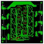
Provided that I use power transformer step switching (for this there is a step switch with power relays, (picture of transformer secondary tap switching circuit board drawing is attached), unfortunately I do not have a tap-switching circuit diagram to provide, because it is drawn by hand on paper, but its working principle is quite simple - the output voltage from output of the power stabilizer controls tap switching relays as needed, switching them on and off in series, at least the 1st secondary winding of the transformer is always switched on and when the output voltage is increased above the value set by the zener regulator, the next winding is switched in series and so on, as the voltage decreases, it is switched off in the same way and excessive secondary windings, it allows to reduce the maximum losses during linear stabilization.
This part has been tested and works, but the power supply stabilizer (described also here: http://www.a-and-t-labs.com/K2_Lab_Power_Supply/ ) itself, which deals voltage and current regulation, gives me a headache. Since the maximum input voltages I use are about 3 times higher than those given in the referenced circuit, this would require changing circuitry - unfortunately, I'm a hobbyist and not strong in theory, so I'm in trouble and can't move forward with it.
The D3, D4 stabilitrons (from this circuit here: http://www.a-and-t-labs.com/K2_Lab_Power_Supply/powersupply_ckt_layout.pdf ) that track supply voltage of IC2 LF357 obviously need to be replaced, but have I confused myself or do I not understand starting point - on the basis of which I determine their stabilization voltages? Also R6, R7, R8 - I couldn't find an explanation of these elements in the article.
I have a power supply built according to this circuit and it has proven itself over about a decade of use without any errors. So I have taken this circuit (for some reason?) as an possible solution.
I don't object if the experts think that this is not a very good solution, but would someone please guide me in my questions, which I am having trouble with.
Or if someone can offer me a better solution, say 0...10 (not exactly strictly needed "0" but say also from 10Vdc is good) to 120VDC adjustable, current limiting PSU (however, I don't want to acquire exotic parts, it is also 100% important that I can use the existing power transformer and as a current stabilizer it would be best also if I can use existing PNP bipolar transistors - otherwise I am open to other options for such a power supply I could perhaps do it with less brain gymnastics).
I have looked in some service manuals of older, higher voltage regulated laboratory power supplies (for example by HP) but they are all based on primary side SCR circuitry and quite different in stabilization stage - could someone shed some light on me, why the use of an SCR preregulator is so preferred? Is it possible that my 6-stage switching method I designed is not a good solution? I don't need extremely high reliability compared to a well-known manufacturer's device, I just need a stabilized, current-limiting power supply with a relatively large adjustment range and higher current, also which I can built at home at the end of my knee, even with the hobbyist's limited resources (to ~200 euros+all existing components) in mind.
In existing parts:
1. Power transformer: 2.5kVA with 6 equal, 19V sec. windings, each consists 4 wires in parallel, 2mm diameter - so, good current capacity
2. I also have a 27000uF/200V capacitor bank as a power filter.
3. 100A bridge rectifier (4 stud mountable 1200V diodes with hardware),
all the necessary passive components for use in the referenced schematic ( http://www.a-and-t-labs.com/K2_Lab_Power_Supply/powersupply_ckt_layout.pdf )
additional:
*digital panel amps (for input AC and output DC) and voltmeters,
*power transformer inrush soft start circuitry,
*probably ~90% or more of the referenced schematic elements.
Once again, I note that I have built the referred 0-50V and about 0-10A output current capability power supply 100% independently (since making of printed circuit board+100% build by only my hands), but to obtain a higher voltage, I feel that my theoretical knowledge leaves me in trouble, so I am asking for helpful guidance from the experts here.
I apologize if my request for help is stupid, I also apologize for the typos. I don't write english in my native.
Thanks for any help!
I have built a couple of lower voltage adjustable power supplies (0-30V and 0-50V in various variations), but I need now a higher voltage and adjustable current limiting power supply.
I have transformer with an 6 equivalent secondary voltage windings which are all with 4 wires parallel, diameter 2mm, all of these 6 windings provide equivalent 19Vac, with a power of about 2.5kVA (big toroidal transformer), so the transformer also allows a fairly large current.
The plan is to use it in the March 1990 issue of Radio Electronics https://archive.org/details/radio_electronics_1990-03 on pages 31 to 34 and page 69 in a "modification" of this power supply described by Reinhard Metz.
But since my transformer can provide significantly higher secondary voltage, I have given up on idea of using the LM317HVK high-voltage stabilizer.
Because I have an LR8N3-G adjustable voltage stabilizer that I would like to use because it technically meets the voltage requirements, - if it can be used?
(datasheet: https://ww1.microchip.com/downloads/en/DeviceDoc/20005399B.pdf )
Also I have 24 PNP-bipolar power transistors 2SA1962, 230V/15A to stabilize current, (datasheet: https://toshiba.semicon-storage.com...et_en_20131101.pdf?did=20429&prodName=2SA1962 )
There is a suitable 6 rack unit case which rear wall is almost entirely huge heatsink, the total area of the heatsink is about 25.000cm2 (close to 4000 sq.in) so it shouldn't be a problem to exchange lot of heat, generated during the stabilization in the worst case in linear mode?
Provided that I use power transformer step switching (for this there is a step switch with power relays, (picture of transformer secondary tap switching circuit board drawing is attached), unfortunately I do not have a tap-switching circuit diagram to provide, because it is drawn by hand on paper, but its working principle is quite simple - the output voltage from output of the power stabilizer controls tap switching relays as needed, switching them on and off in series, at least the 1st secondary winding of the transformer is always switched on and when the output voltage is increased above the value set by the zener regulator, the next winding is switched in series and so on, as the voltage decreases, it is switched off in the same way and excessive secondary windings, it allows to reduce the maximum losses during linear stabilization.
This part has been tested and works, but the power supply stabilizer (described also here: http://www.a-and-t-labs.com/K2_Lab_Power_Supply/ ) itself, which deals voltage and current regulation, gives me a headache. Since the maximum input voltages I use are about 3 times higher than those given in the referenced circuit, this would require changing circuitry - unfortunately, I'm a hobbyist and not strong in theory, so I'm in trouble and can't move forward with it.
The D3, D4 stabilitrons (from this circuit here: http://www.a-and-t-labs.com/K2_Lab_Power_Supply/powersupply_ckt_layout.pdf ) that track supply voltage of IC2 LF357 obviously need to be replaced, but have I confused myself or do I not understand starting point - on the basis of which I determine their stabilization voltages? Also R6, R7, R8 - I couldn't find an explanation of these elements in the article.
I have a power supply built according to this circuit and it has proven itself over about a decade of use without any errors. So I have taken this circuit (for some reason?) as an possible solution.
I don't object if the experts think that this is not a very good solution, but would someone please guide me in my questions, which I am having trouble with.
Or if someone can offer me a better solution, say 0...10 (not exactly strictly needed "0" but say also from 10Vdc is good) to 120VDC adjustable, current limiting PSU (however, I don't want to acquire exotic parts, it is also 100% important that I can use the existing power transformer and as a current stabilizer it would be best also if I can use existing PNP bipolar transistors - otherwise I am open to other options for such a power supply I could perhaps do it with less brain gymnastics).
I have looked in some service manuals of older, higher voltage regulated laboratory power supplies (for example by HP) but they are all based on primary side SCR circuitry and quite different in stabilization stage - could someone shed some light on me, why the use of an SCR preregulator is so preferred? Is it possible that my 6-stage switching method I designed is not a good solution? I don't need extremely high reliability compared to a well-known manufacturer's device, I just need a stabilized, current-limiting power supply with a relatively large adjustment range and higher current, also which I can built at home at the end of my knee, even with the hobbyist's limited resources (to ~200 euros+all existing components) in mind.
In existing parts:
1. Power transformer: 2.5kVA with 6 equal, 19V sec. windings, each consists 4 wires in parallel, 2mm diameter - so, good current capacity
2. I also have a 27000uF/200V capacitor bank as a power filter.
3. 100A bridge rectifier (4 stud mountable 1200V diodes with hardware),
all the necessary passive components for use in the referenced schematic ( http://www.a-and-t-labs.com/K2_Lab_Power_Supply/powersupply_ckt_layout.pdf )
additional:
*digital panel amps (for input AC and output DC) and voltmeters,
*power transformer inrush soft start circuitry,
*probably ~90% or more of the referenced schematic elements.
Once again, I note that I have built the referred 0-50V and about 0-10A output current capability power supply 100% independently (since making of printed circuit board+100% build by only my hands), but to obtain a higher voltage, I feel that my theoretical knowledge leaves me in trouble, so I am asking for helpful guidance from the experts here.
I apologize if my request for help is stupid, I also apologize for the typos. I don't write english in my native.
Thanks for any help!
Attachments
Last edited:
Hi your post is hard to read with much information. Maybe you can use numbers or dots for each question?
https://justanotherelectronicsblog.com/?p=846
https://justanotherelectronicsblog.com/?p=846
^Agreed. A circuit scribble of what you would want to do is useful - a circuit board layout isn't.
Jan
Jan
What is wrong with circuit board? This is not regulator board but transformer switching board, it is different thing but I don't have regulator board ready because it is not exactly like in circuit referred to.
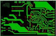
The previously built 0-50V power supply unit is 1:1 with a similar printed circuit board in terms of content described this magazine, but I cannot fit for example power filter capacitor bank and bridge rectifier on to regulator PCB. So I'll probably be making a lot more changes to this voltage/current regulator circuit board.
In the following attachment, there is a picture of the existing 50V power supply 1. version circuit board (almost exactly like in magazine), but as I already mentioned - in the case of this much higher voltage version, even if I can use the LR8N3-G adjustable regulator, then obviously I have to change this board because the IC2 circuit components also need to be changed - this is my question.
If I feed existing one to nearly 160V then sure that it does not work.
But - what's wrong with my tap-switching board? It works in real life, at least when feeding test voltages, relays switch just as needed.
Attachments
Jan D. probably means you should show a schematic. Not many like to read a PCB. That is like switching on the TV to listen radio.
It forces readers to put more energy in it than usual so more than double the brain gymnastics and ... more than double the time. This is not in the interest of both the asker and the answerer. So please attach a schematic and pose questions please with either letters, numbers or dots. A more or less logical sequence also helps.
* Some people write items like they think, this is very hard to follow for many. Just some hints to make you get the answers you're seeking. I know for sure that your fist post will be skipped by many, regardless of language/language barriers.
Last edited:
Sorry, circuit diagram is just reference, again:
http://www.a-and-t-labs.com/K2_Lab_Power_Supply/powersupply_ckt_layout.pdf
But - in this case it needs to be modified to work up to about 150Vdc input voltage, thats my biggest concern - maybe someone help and can give me some tips on what to change so that it works at a 150Vdc (in reality, nearly 160Vdc) input voltage?
You ask a question. You show a circuit board that's totally irrelevant to the answer you need. What am I supposed to do, trying to unravel a PCB while having no idea what it is supposed to be? Really.What is wrong with circuit board? This is not regulator board but transformer switching board, it is different thing but I don't have regulator board ready because it is not exactly like in circuit referred to.
The previously built 0-50V power supply unit is 1:1 with a similar printed circuit board in terms of content described this magazine, but I cannot fit for example power filter capacitor bank and bridge rectifier on to regulator PCB. So I'll probably be making a lot more changes to this voltage/current regulator circuit board.
In the following attachment, there is a picture of the existing 50V power supply 1. version circuit board (almost exactly like in magazine), but as I already mentioned - in the case of this much higher voltage version, even if I can use the LR8N3-G adjustable regulator, then obviously I have to change this board because the IC2 circuit components also need to be changed - this is my question.
If I feed existing one to nearly 160V then sure that it does not work.
But - what's wrong with my tap-switching board? It works in real life, at least when feeding test voltages, relays switch just as needed.
Jan
This supply takes an AC from the transformer to make DC and regulate that. If you say 150VDC input (or 160VDC, please make up your mind), what do you mean? You mean a different xformer so that it gives 160VDC rectified, and then regulated to which output voltage?Sorry, circuit diagram is just reference, again:
http://www.a-and-t-labs.com/K2_Lab_Power_Supply/powersupply_ckt_layout.pdf
But - in this case it needs to be modified to work up to about 150Vdc input voltage, thats my biggest concern - maybe someone help and can give me some tips on what to change so that it works at a 150Vdc (in reality, nearly 160Vdc) input voltage?
If you want 120VDC output, 150VDC input will work but is a bit high, will give a lot of dissipation.
Anyway, you will need another xformer, instead of the 42VAC secondaries you'll need something like 100VAC secondaries.
If you want just a single supply you could use both 42VAC windings in series for 84V which will get you close.
So it all depends on what you want.
The best way to get this going is to decide what you want at the output and then work backwards to find what you need to make that happen.
Jan
Last edited:
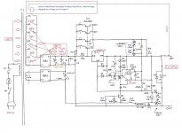
1. So, the little modified diagram is attached - hope that discussion for heat dissipation, etc. will skipped now
2. I wrote 150Vdc and 160Vdc as input voltage really and my bad but because I assume that if I write that the alternating Voltage from the transformer is 114V in the maximum case, then 114x1.41= approximately 160Vdc if smoothed by filtering capacitor.
Why did I write then 150V? because if someone thinks that 160Vdc is not good etc. and 150Vdc suits them better, then I know there is a certain type of peoples who doesn't even bother to think along because they think that the questioner is stuck on a certain path - NO, it isn´t! If someone has a better linear regulator solution then for god forbid - I'll check it out.
If this voltage is too high, let's say 5V, to work then I have no problem not using one secondary less and get a little lower (approx. 134Vdc) max input voltage to regulator.
Yes, ideally I could use a maximum of all possible 6 windings, 160Vdc minus the losses on the regulator, so 150V seems to be nearly realistic maximum output Voltage from PSU.
However, I would be satisfied with 0(approx.)V to 120Vdc if someone thinks that more is "dangerous", "does not meet a Euro bs requirements" or etc.
In short, it is not in place with quartz, but I don't also want to do a complete U-turn.
3. No, any "2 or 3 or more LM317HV regulator in series" is completely ruled out because I don't have any extra LM317HV at this moment and mouser gives 88 weeks lead time. So, no, LM317 is passed stage and time to move forward.
Attachments
I would ditch the schematics you have, and go for a supply with two comparator opamps. Examples of this are Delta elektronika E030-1 which can be increased in both voltage and current to suit your requirements.
If you need any help with this, i would be quite happy to draw you a schematic, but i need the expected requirements for the supply.
If you need any help with this, i would be quite happy to draw you a schematic, but i need the expected requirements for the supply.

This? https://nvhrbiblio.nl/schema/Delta_E030-1.pdf
Seems quite considerable, but there is one thing - in component list I can also see some very big differences with some component values depending on PSU output parameters.
I absolutely do not want to give up power transformer secondary windings step switching as this would greatly reduce the regulator losses.
At lower voltages I know there are industrial power supplies that switched the secondary windings from 15V to next level and allowed up to 30V output voltage and less heat.
I've been thinking that why I haven't come across any powerful (over kW or more) power supply unit with step switching of the secondary windings, maybe there is this "thing" then😳 - circuit will become excessively complicated if you try to do it with for example, like I try to do, 6-step PRE-REGULATOR?
Given that my transformer outputs 114V alternating voltage, then the direct voltage from PSU output could be adjustable from 0 to 140-150Vdc and the maximum current for example in range 0-12A (4 wires in parallel, each with a diameter of 2mm is not an obstacle in ensuring this).
Based on SOA of 2SA1962 and paralleling 24 of them (they are new, from one factory tube) this 12A seems allowable - but only with staged pre-regulator..
If I can't use step-switching of transformer secondary windings with reasonable regulator complexity, then such a power supply becomes really pointless in the case of low output voltage and high current, because for example, with 3V output (if i need this) voltage and 10A current. I wouldn't really want to turn remaining 147V and high current to heat, but about 20V to heat (if I can use step switching) wouldn't really be a any big loss.
Yes that delta schematic with the opamps is what i was referring to. You can lift the control electronics from that, and use a skizlai pair for the outputs driven by a NPN
The problem with range switching is that if you take a mechanical switch you will kill the contacts with the capacitor charging peaks. Not even speaking of the EMI that will produce. If you want thyristor regulation you need to source a EI core inductor that weights more than the toroidal transformer, and its power factor is 0.5 maximum meaning you cannot get the 12A required that way.
What you could do, and this is oldschool, is to take a variac and gang the voltage set pot and the variac.
But truth be told your likely better off buying an off-the shelf switching power supply for this kind of power. its likely cheaper.
You could build a 0-300V 0-200mA power supply just for good measure, but the supply you are envisioning is too complicated for a hobbyist to pull off successfully.
OK yes that will work. At least now we know what you want to do.1. So, the little modified diagram is attached - hope that discussion for heat dissipation, etc. will skipped now
2. I wrote 150Vdc and 160Vdc as input voltage really and my bad but because I assume that if I write that the alternating Voltage from the transformer is 114V in the maximum case, then 114x1.41= approximately 160Vdc if smoothed by filtering capacitor.
Why did I write then 150V? because if someone thinks that 160Vdc is not good etc. and 150Vdc suits them better, then I know there is a certain type of peoples who doesn't even bother to think along because they think that the questioner is stuck on a certain path - NO, it isn´t! If someone has a better linear regulator solution then for god forbid - I'll check it out.
If this voltage is too high, let's say 5V, to work then I have no problem not using one secondary less and get a little lower (approx. 134Vdc) max input voltage to regulator.
Yes, ideally I could use a maximum of all possible 6 windings, 160Vdc minus the losses on the regulator, so 150V seems to be nearly realistic maximum output Voltage from PSU.
However, I would be satisfied with 0(approx.)V to 120Vdc if someone thinks that more is "dangerous", "does not meet a Euro bs requirements" or etc.
In short, it is not in place with quartz, but I don't also want to do a complete U-turn.
3. No, any "2 or 3 or more LM317HV regulator in series" is completely ruled out because I don't have any extra LM317HV at this moment and mouser gives 88 weeks lead time. So, no, LM317 is passed stage and time to move forward.
There's some details to work out of course but the concept is sound.
Did you see the T-reg in the diyaudio store? That can be adjusted from 0 to whatever the input voltage is with adjustable current limit.
https://diyaudiostore.com/collections/power-supplies-accessories/products/linear-audio-t-reg
It has much less ripple and output Z than a 317-based design because it does not have to amplify the reference of 1.25V. In the T-reg, the reference is the same as the output voltage.
Jan
I would use a TL431 voltage ref on the op amp and a pnp driver instead of the regulator chip.
Compensate the op amp with 1000pf cap and let it do the work
Compensate the op amp with 1000pf cap and let it do the work
That 1000pF will seriously cripple it.
What reference voltage would you set that TL431 to? Lets say 15V, and the output should be 150V. That means that the opamp has to amplify that ref voltage by 10 or 20dB. That 20dB comes out of the loop gain.
Compared to a ref of 150V (as would be the case in the T-reg) that means that the performance is 10x or 20dB less.
20dB less ripple rejection, 10 x higher Zout, you get the point.
Jan
Is T-reg. something similar to ST microelectronics VB408?
data here: http://pdf.datasheetcatalog.com/datasheet/stmicroelectronics/6421.pdf
Yours seems more complicated than the VB408, while all these mentioned are adjustable regulators, but the more complicated part is that part which allows these regulators to be controlled correctly to ensure, for example, the pre-setting of current limiting, while taking into account that this whole sensitive part would tolerate this increase/decrease of the input voltage.
E: Theoretically i have discrete elements to made VB408 subcircuits, this circuit was described by ETH quantumoptics. If VB408 or precisely its subcircuit regulator, made from discrete element base is more preferable, I am ready to use this if it change something to better way?
Last edited:
You seem to want a full-blown lab-supply, with V variable from 0 to Vmax, and I from 0 to Imax. No ready-made IC will be able to do that by itself. In the seventies, Motorola had a rare circuit designed precisely for that, but it required lots of discretes and was limited to ~35V.
It had little success, and was discontinued decades ago.
For high voltages, the problem is even more complicated, and you need to rely on custom designs.
Elektria is such a supply, and can easily be tailored to the specs you want: voltage, current, accuracy, stability depending on the configuration and components you use. An advantage is its extreme efficiency: it is in fact a HV LDO.
https://www.diyaudio.com/community/...supply-truly-diy-friendly.330193/post-5606157
Another example is the linear part of this whacky supply: you can dispense with the insane switching front-end, and just use the linear post-regulator (with suitable power elements and heatsinking).
https://www.diyaudio.com/community/...le-supply-on-a-shoestring.230360/post-3391358
I have designed many other HV variable supplies (including the ones I use the most often in my lab), but their documentation is scant, for personal use only, and not in an electronic format which means I cannot share them.
The specs of these variable supplies are not of an ultra-high standard: with a targeted design, <µV noise and µohm impedance level is achievable, but in general you want a lab supply to be an easy, two-wire only device you can connect with simple banana plugs and alligator clips
Yes, it is closest to a laboratory adjustable power supply unit but i dont need ultra good stability etc.
Do you mean MC1466 single chip current/voltage controller?
LM723 also nearly comparable? Those LM723 I have also some left but they are good only around 30V or some cases to 50V.
This Reinhard Metz reference design 0-50V is not bad and has worked for a long time and I am satisfied with it, but a larger voltage and current range is needed.
I haven't measured (how could it be done correctly, standardly?) but I have several DIY and also modern commercial lab power supply units with different voltages and currents.
0-30; 4-35V; 0-50V [LM317, 317AHVT, all of which also have adjustable current limiting, LM338, LT1038 which bot have only adjustable voltage but pretty good current capability and small, they are all DIY-built and newest is from factory products 0-60V and 0-5A Wanptek NPS605W, modern adjustable, smps based lab psu.
I had the parts described above, that's where all the activity around this 2.5kVA transformer linear power supply started. Too late I came across a DIY-friendly SMPS lab psu design that would have been easier to adapt, but when I look at this large and good case and the preparations already made and the existing transformer, it would be a sin not to use these existing parts.
I have also looked this: http://hpm-elektronik.de/ng350-0400-netzteil.htm which in theory might even seem ideal - considering that I can divide the secondary windings of the transformer in half if I wish, and therefore also increase all voltages by 2x, and it seems to me that this scheme would allow me to operate the step switch of the secondary winding more easily.
Fortunately, no one has YET asked me what is the field of use of this relatively powerful current source - very large part of the need for voltage over 100Vdc is actually electrochemistry - the oxidation of non-magnetic light metals. Yes it could be done much more easily, but I would like to do it once and properly.
I will continue with one method or another, another crazy extreme that has crossed my mind would be to use together with switching voltage stages of power transformer, also switching corresponding circuit elements with different input voltage values at different levels, perform this task with miniature relays (I have a bit of an overabundance of them). Crazy idea..
However, in this regard, I did not have an idea that would help to eliminate interruptions in the circuits of the operational amplifier that occur at the moment of component switching, so I am trying to think about finding a possible solution to this problem.
Is it hard to believe that an adjustable power supply with such structure has not been created in the world?
E:
Is it possible to find a service manuals for the huge and heavy: TDK Lambda, Electronic Measurements, etc. somewhere? They look really big and brutal in the pictures, I believe I'm looking something like that but an easier DIYable and "domesticated" solution, without bells and whistles.
Some of them that I have been able to examine from the photos seem to contain a large massive mains transformer, and therefore it is possible that some tips might be obtained from.
For example like this: https://accusrc.com/uploads/datasheets/5625_TCR Series.pdf or TDK Lambda ESS serie etc.
Do you mean MC1466 single chip current/voltage controller?
LM723 also nearly comparable? Those LM723 I have also some left but they are good only around 30V or some cases to 50V.
This Reinhard Metz reference design 0-50V is not bad and has worked for a long time and I am satisfied with it, but a larger voltage and current range is needed.
I haven't measured (how could it be done correctly, standardly?) but I have several DIY and also modern commercial lab power supply units with different voltages and currents.
0-30; 4-35V; 0-50V [LM317, 317AHVT, all of which also have adjustable current limiting, LM338, LT1038 which bot have only adjustable voltage but pretty good current capability and small, they are all DIY-built and newest is from factory products 0-60V and 0-5A Wanptek NPS605W, modern adjustable, smps based lab psu.
I had the parts described above, that's where all the activity around this 2.5kVA transformer linear power supply started. Too late I came across a DIY-friendly SMPS lab psu design that would have been easier to adapt, but when I look at this large and good case and the preparations already made and the existing transformer, it would be a sin not to use these existing parts.
I have also looked this: http://hpm-elektronik.de/ng350-0400-netzteil.htm which in theory might even seem ideal - considering that I can divide the secondary windings of the transformer in half if I wish, and therefore also increase all voltages by 2x, and it seems to me that this scheme would allow me to operate the step switch of the secondary winding more easily.
Fortunately, no one has YET
asked me what is the field of use of this relatively powerful current source - very large part of the need for voltage over 100Vdc is actually electrochemistry - the oxidation of non-magnetic light metals. Yes it could be done much more easily, but I would like to do it once and properly.I will continue with one method or another, another crazy extreme that has crossed my mind would be to use together with switching voltage stages of power transformer, also switching corresponding circuit elements with different input voltage values at different levels, perform this task with miniature relays (I have a bit of an overabundance of them). Crazy idea..
However, in this regard, I did not have an idea that would help to eliminate interruptions in the circuits of the operational amplifier that occur at the moment of component switching, so I am trying to think about finding a possible solution to this problem.
Is it hard to believe that an adjustable power supply with such structure has not been created in the world?
E:
Is it possible to find a service manuals for the huge and heavy: TDK Lambda, Electronic Measurements, etc. somewhere? They look really big and brutal in the pictures, I believe I'm looking something like that but an easier DIYable and "domesticated" solution, without bells and whistles.
Some of them that I have been able to examine from the photos seem to contain a large massive mains transformer, and therefore it is possible that some tips might be obtained from.
For example like this: https://accusrc.com/uploads/datasheets/5625_TCR Series.pdf or TDK Lambda ESS serie etc.
Yes, that's the one.Do you mean MC1466 single chip current/voltage controller?
There are many ways to skin a cat, and people at Lambda and elsewhere know how to do it, for sure.
Very often though, these professional supplies use multiple auxiliary supplies, which require a custom transformer.
Did you look at boat anchor manuals?
I don’t know why people seem to always be hung up on 3 terminal regulators for making hundred volt supplies. By the time you wrap everything you need to safely run them around them you could very well build a discrete solution with a precision op amp front end. And then not worry about the 40 or 57 volt differential rating. Transients and faults can easily cause it to be exceeded.
if the transformer has the multiple taps run it in a class H -ish mode. That will take care of the SOA problem. For the one to ten microseconds required for the switching between rails, any power transustors worth buying will handle the transient dissipation condition, as long as there is enough VCEO.
if the transformer has the multiple taps run it in a class H -ish mode. That will take care of the SOA problem. For the one to ten microseconds required for the switching between rails, any power transustors worth buying will handle the transient dissipation condition, as long as there is enough VCEO.
- Home
- Amplifiers
- Power Supplies
- Brain gymnastics to construct around 120V and up adjustable power supply.