This is a bit hand-waving unless you explicitly state the frequency range you mean by "low frequencies". Under 50Hz? Under 100Hz? Under 500Hz?
It was stated: "at low frequencies the wavelength of sound is large compared to the cabinet ". In acoustics this way of bounding assumptions is common.
In truth these days for simulations on a home PC the near field of a speaker can be accurately simulated upto about 2-5 kHz depending on what one is considering with higher only being a question of computing resource. With a known near field getting to the far field is straightforward (e.g. like the Klippel). On a home PC including the room in the simulation obviously pulls the resolved frequency down a fair bit but one can usually get above the Schroeder frequency. Above this frequency approximate methods of simulating the radiation can give OK(ish) results for rooms that don't exist or have yet to include modifications.
As mentioned in another thread I will soon start posting on the subject of loudspeakers and engineering. The initial topic is sorted and based on sound radiation from vibrating cabinets. I am on the look out for other subjects of interest though and there seems to be one here although I am not sure quite what it is. What is going on in the near field of speaker perhaps? Suggestions welcome.
Can you lay out an actual method, or workflow, to do this? With a real-life demonstration?In truth these days for simulations on a home PC the near field of a speaker can be accurately simulated upto about 2-5 kHz depending on what one is considering with higher only being a question of computing resource. With a known near field getting to the far field is straightforward (e.g. like the Klippel). On a home PC including the room in the simulation obviously pulls the resolved frequency down a fair bit but one can usually get above the Schroeder frequency. Above this frequency approximate methods of simulating the radiation can give OK(ish) results for rooms that don't exist or have yet to include modifications.
Last edited:
They are not my methods, they are the methods used by acoustical engineers in industry today. It would be rather embarrassing if I was wrong given some of my previous day jobs but it is a possibility. I am based in Europe and so there are practical issues but if it is a question of comparing simulations and measurements then simulations can be posted. Could make a nice article on the relative accuracy of simulations of various kinds and measurements of various kinds when it comes to loudspeakers. Fair bit of work though and it will have to come after the sound radiation from cabinets I am currently working on. What would you suggest as a reference? Working it into an open group DIY project might fit nicely?So, if you're one saying that the NFS isn't necessary, it might be fun to test your design on the NFS and then compare the results. You might be right. Maybe your methods are good enough. But odds are, you're going to find you're wrong. Not being snarky. I'm speaking purely from experience without any malice.
PS Not sure what I did wrong with my previous post but this is what I thought I had posted.
Can you lay out an actual method, or workflow, to do this? With a real-life demonstration?
That is what will be posted on the website. If there is some interest I will likely continue with it for a while or, perhaps, involve others. I don't expect a large amount of interest or else DIYers would be doing this sort of thing already. KEF posted typical examples of engineering simulations in their recent white papers on the LS50 and LS60. They likely used different software but the modelling and methods will be essentially the same.
Would the Geoff Hill chamber offer any advantages?
So this was a cool idea! But limited to taking measurements of a single driver. I don't see how it would be adapted to whole loudspeaker. Although I wonder if you had the speaker far enough away so the mic could "see" the whole speaker, would this also reduce reflections getting to the mic?
IMHO one of the biggest loudspeaker measurement challenges is in the range of 200-800Hz. Here you can have cabinet and driver resonances, but it is difficult to get very high resolution measurements without resorting to ground plane or elevating the speaker far above the ground, or using a large anechoic chamber.
Below 100-200Hz things get easier again.
I agree Charlie,
sub range is relatively easy, as those frequencies usually come from near the ground plane.
but the 200-800Hz range is tough to nail down.
For the reasons you mention in a following post.....
either the need to tilt the speaker towards the mic on the ground and who listens at ground plane anyway,
or how do you pragmatically get away from ground bounce without a substantial speaker tower and flown mic to boot. And try to put a turntable on that kinda of rig !! Or even get the speaker up on the tower !!! LOL
Speaker on a turntable pointing off the back of my deck to an open space, and a boom from the deck holding the mic, gives about 25-30 ms fairly reflection free.
It's the best I've come up with so far....works pretty well...... until the wind blows any at all 😡
There is usually a strong correlation between manufacturers that use FEA/BEM type of simulations in their design stages and getting the response they wanted without any odd surprises. The alternative is someone with a great deal of practical experience and access to good anechoic measurements.I'd say many, many of them are going to be off by a fair bit. Most notably what I find is baffle step influence (not just baffle step but the influence combined with other things like port resonances). Manufacturers such as Kef and Revel/JBL don't tend to have this issue. But they're unfortunately the exception, based on my direct experience.
What you say about baffle step is true, you have to consider all the dimensions of the box and driver and if you don't the response will change.
Here is an example of the difference in a normalized polar plot of changing the cabinet depth from 200 to 400mm, everything else remained the same.
Most DIY designs still seem to be stuck at the single axis measurement with a 3 - 5ms gate. This hides a multitude of sins. The NFS is a great device and a good arbiter of truly determining what you have particularly, frequency response and directivity. I think there is room there in between those positions for a determined person to get "close enough", but it would certainly take a lot of time and effort and experience. Your own thread of "How close is close enough" shows that struggle.So, if you're one saying that the NFS isn't necessary, it might be fun to test your design on the NFS and then compare the results. You might be right. Maybe your methods are good enough. But odds are, you're going to find you're wrong. Not being snarky. I'm speaking purely from experience without any malice.
If the NFS was $10,000 I suspect there would be a whole lot of them out there, at $100,000 (or more with all the extras), it is unobtainable for 99% of DIY'ers. For myself and I suspect most other serious measurement oriented hobbyists or small manufacturers, I want to find a way to get close enough with what I can afford.

Hopefully it proves useful!The issue, which as been adressed in the Klippel on shoestring thread, is whether there are cheaper ways to skin the cat. That has also been the topic on ASR. Member Aslepekis seems to have gotten fairly close to the Klippel measurements in Shoestring thread.
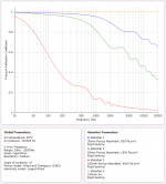
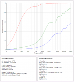
For anyone who hasn't seen the latest posts in that thread, by summing multiple measurement points taken along an axis it is possible "tune out" the unwanted reflections. How well it works depends on how many reflections need to be contended with, and how energetic they are. It's certainly not the same as the NFS (and I still want to see a DIY NFS) but this method can get high resolution data down to a few hundred Hertz or lower and be done with REW and whatever hardware you already have on hand. Below are the results of that method: black is a Behringer Truth B2030P as measured by Amir at Audio Science Review on his Klippel NFS, red is one of my own 2030P's using this method with 20 measurement points, blue is with only 4. No smoothing or IR window has been applied. Differences at higher frequency may be due to unit to unit variation.
I won't derail this thread anymore, but there are some refinements I plan on posting about on the Nearfield Scanner on a Shoestring thread.
Interesting work, thanks! How are you summing the responses? Do you apply HBT to create minimum phase? Summing responses is easy in Soundeasy, but the different phases would not allow it to sum constructively. Unless (I think) I applied HBT to bring them all to minimum phase first.
Happy to share!
I'm using vector averaging in REW to do the summation. Without a loopback active, REW will keep all the IR peaks aligned and they will sum constructively. That's all I've done for processing. I had been exporting the Impulse Responses and summing them in Audacity, but I got the same results with vector averaging natively in REW.
And please feel free to share any suggestions for improvement.
My idea of how a DIY Klippel might be constructed hit a significant snag recently and it made me think of trying something like this in between the speaker and mic.Cool, I await your results!
https://www.researchgate.net/public...anechoic_linings_Optimization_and_application
Basic a flat absorber where the density gradually increases so you don't get a reflection which is the reason why wedges are used in a lot of anechoic chambers.
An example I made up using the calculator here that is 330mm deep plus 100mm air gap http://www.acousticmodelling.com/multi.php
These are separated out to make it easier to see the individual combinations, when they are combined in the one box the result gets slightly better
Attachments
If one look at this result and think about how a speaker is used in a normal room, how could a NFS have helped this results? If it works in one direction, it works in all other - i.e. one can design and verify a product as well as with NFS less +/- a dB (or two). Thinking more about how to get good sound in peoples homes, NFS is not what is going to do it but rather a system that helps the end user to EQ the reproduction into a suitable tight specification.Hopefully it proves useful!
For anyone who hasn't seen the latest posts in that thread, by summing multiple measurement points taken along an axis it is possible "tune out" the unwanted reflections. How well it works depends on how many reflections need to be contended with, and how energetic they are. It's certainly not the same as the NFS (and I still want to see a DIY NFS) but this method can get high resolution data down to a few hundred Hertz or lower and be done with REW and whatever hardware you already have on hand. Below are the results of that method: black is a Behringer Truth B2030P as measured by Amir at Audio Science Review on his Klippel NFS, red is one of my own 2030P's using this method with 20 measurement points, blue is with only 4. No smoothing or IR window has been applied. Differences at higher frequency may be due to unit to unit variation.
View attachment 1091166
I won't derail this thread anymore, but there are some refinements I plan on posting about on the Nearfield Scanner on a Shoestring thread.
Its is important that directivity is even (/ the desired) and distorsion is low than that a speaker has a flat/linear FR out of the box. To verify this does not take a Klippel NFS.
FR is best corrected on location, for the listening position - which varies wildly more than the NFS vs. DIY measurement error anyways.
It just don't make sense - but ohh, is it a piece of sexy equipment... almost like a high end amplifier.... ;-) cmon, this is mostly gear obsession... again...
//
@TNT
Time to revisit Toole’s book, specifically 5.6.2, the one that starts:
“The notion that a single curve resulting from sounds picked up by an omnidirectional microphone is an adequate representation of perceptions by two ears and a brain is preposterous. It is related but incomplete data. A prediction of a room curve from anechoic data allows one to identify what the room is doing to the sound.”
Because direct sound will dominate the sq it is erroneous to think that frequency response above the transition frequency can be corrected by anything other than anechoic data. If you want to dispute Toole you’re welcome, but it’ll take a bit more than snide remarks to convince me.
Last edited:
Its is important that directivity is even (/ the desired) and distorsion is low than that a speaker has a flat/linear FR out of the box. To verify this does not take a Klippel NFS.
FR is best corrected on location, for the listening position - which varies wildly more than the NFS vs. DIY measurement error anyways.
It just don't make sense - but ohh, is it a piece of sexy equipment... almost like a high end amplifier.... ;-) cmon, this is mostly gear obsession... again...
//
Below are the results of that method: black is a Behringer Truth B2030P as measured by Amir at Audio Science Review on his Klippel NFS, red is one of my own 2030P's using this method with 20 measurement points, blue is with only 4. No smoothing or IR window has been applied. Differences at higher frequency may be due to unit to unit variation.
Interesting to see the Behringer 2030P used as a reference. It has a low price and is still a current model.
To be clear - I'm talking about the last +/- 1 dB. Which is the size of the errors we seem to be talking about here. A well designed speaker is fairly linear also FR wise of course. A modern one contains DSP functions.This is directly contrary to Toole and goes to the validity of the NFS.
//
Last edited:
Because direct sound will dominate the sq it is erroneous to think that frequency response above the transition frequency can be corrected by anything other than anechoic data.
If you know the pressure and particle velocity on a surface containing all the sound sources then a Kirchoff integral will give you the far field (i.e. "anechoic data"). This is widely used in acoustics and other fields in all sorts of places and has been for a long time. In practise there are errors associated with how you obtain pressure and particle velocity, how close the known values are on the surface, plus one or two other things but the approach is quite valid.
Last edited:
- Home
- Loudspeakers
- Multi-Way
- How much would YOU pay for Klippel service?