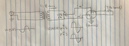
A recent thread asking for confirmation of balanced operation in a preamp-looking thing got me thinking about an 'unbal' I'd just made, and got me wondering whether it in fact generated balanced output. The unbal applies unbalanced RCA line level input directly to the primary of a 1:8 turns ratio line level transformer, and takes output from across the wiper of a 50k pot (connected to XLR pin 2, "+") and the presumed 'no dot' end (connected to XLR pin 3, "-") of the transformer secondary (see the sketch below). Mark Johnson suggested to the OP of that earlier thread that generating and testing a hypothesis would be a good approach to answering such a question.
Hypothesis: In response to the input of an unbalanced sine wave, a true 'unbal' will output sine waves of opposite sign on the + and - pins. Any other outcome suggests the unbal is not producing balanced output.
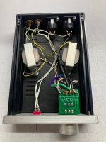
Methods: A signal generator was used to apply a sine wave to the RCA input of the unbal. A 2-channel oscilloscope was first used to visualize the sine wave at the point of generation, then later to visualize the output of the unbal on XLR pins 2 and 3. A loading resistor of 30k ohms was used across pins 2 and 3 to simulate the load of an amplifier. The oscilloscope probes were grounded on XLR pin 3, the floating chassis ground of the unbal, which is not connected to the input RCA ground (ignore the white wires and the ground lift switch in the picture). Both the loading resistor and probe grounding were necessary to generate stable waveforms.
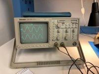
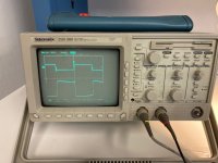
Results: The sine wave output of the unbal was inverted on both pins 2 and 3 relative to the input sine wave. The sine wave outputs showed the expected amplification/attenuation in voltage swing when the pot volume knob was adjusted. The output on pins 2 and 3 were not inverted relative to each other, that is, they were 'in phase'.
Conclusion: The device in question is not functioning as an unbal, as the "-" and "+" outputs are not inverted relative to each other.
***
And so my question for the forum: Is my hypothesis flawed, e.g. is normal balanced output supposed to be in phase or out of phase?
Hypothesis: In response to the input of an unbalanced sine wave, a true 'unbal' will output sine waves of opposite sign on the + and - pins. Any other outcome suggests the unbal is not producing balanced output.
Methods: A signal generator was used to apply a sine wave to the RCA input of the unbal. A 2-channel oscilloscope was first used to visualize the sine wave at the point of generation, then later to visualize the output of the unbal on XLR pins 2 and 3. A loading resistor of 30k ohms was used across pins 2 and 3 to simulate the load of an amplifier. The oscilloscope probes were grounded on XLR pin 3, the floating chassis ground of the unbal, which is not connected to the input RCA ground (ignore the white wires and the ground lift switch in the picture). Both the loading resistor and probe grounding were necessary to generate stable waveforms.
Results: The sine wave output of the unbal was inverted on both pins 2 and 3 relative to the input sine wave. The sine wave outputs showed the expected amplification/attenuation in voltage swing when the pot volume knob was adjusted. The output on pins 2 and 3 were not inverted relative to each other, that is, they were 'in phase'.
Conclusion: The device in question is not functioning as an unbal, as the "-" and "+" outputs are not inverted relative to each other.
***
And so my question for the forum: Is my hypothesis flawed, e.g. is normal balanced output supposed to be in phase or out of phase?
Attachments
OR the pins 1-2 circuit. The output is totally floating. When you put a probe to it you change the conditions. For affordable transformers it is very likely that one side of the winding is dominant.probes were grounded on XLR pin 3, the floating chassis ground of the unbal, which is not connected to the input RCA ground
What frequencies? This rig may be dominated by stray capacitance by even 1kHz.
How does the pot improve your understanding? I would cut it out for testing. (I do understand why you "need" it for a 1:8 step-up, yowsa.) Put two 27k series across the winding and measure each side against the resistors' center tap.

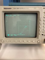
I will likely examine this further. I did get the impression that one end of the secondary showed waveforms a little different than the other, not really evident on sine waves but evident on square waves (first picture). With a square wave input of +/- 11.5kHz, plotting the "dot" of the secondary against the "no-dot" of the secondary using an X-Y plot, I got what looked like a hysteresis curve, which I thought was cool (second picture).OR the pins 1-2 circuit. The output is totally floating. When you put a probe to it you change the conditions. For affordable transformers it is very likely that one side of the winding is dominant.
What frequencies? This rig may be dominated by stray capacitance by even 1kHz.
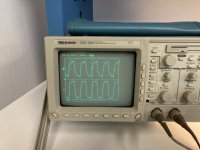
I went from 10Hz to 100kHz out of curiosity with sine, triangle, and square waves, but didn't take systematic notes, which I regret now. Square waves from about 3kHz up appear to cause ringing on the primary which can be picked up at the signal generator, but not on the secondary (edit: third picture).
How does the pot improve your understanding? I would cut it out for testing. (I do understand why you "need" it for a 1:8 step-up, yowsa.) Put two 27k series across the winding and measure each side against the resistors' center tap.
This is similar to the test proposed by JMFahey in another thread. Your point about the grounding on this particular setup being useless from the point of view of completing a circuit is well taken. Using + and - as the floating input to an ACA, I got best sound, however I think when I grounded the scope probe on one and read the sine wave from the other, I got no signal, which would imply that the + and - were in fact nulling each other out? I need to confirm that. More testing required.
Attachments
Hi-Fi guys expect "balanced" to be simple instant gratification.
Old-school broadcast engineers learned to expect hours of debugging/optimization.
Both when transformers ruled, then when various transformerless contraptions took over.
Old-school broadcast engineers learned to expect hours of debugging/optimization.
Both when transformers ruled, then when various transformerless contraptions took over.
The output shown on the sketch is not balanced. The output on pin 3 is almost zero ohms to one of the output leads from a transformer. pin 2 has some resistance from the potentiometer all the way up to 50K. Perhaps some study of what balanced means might be in order. Now are the signals on the output leads of the transformer out of phase with each other? Yes.
I'm aware that the use of a pot in this manner guarantees the impedances on pin 2 and 3 will differ except maybe at full volume, and now understand that the definition of balanced output is not met here. I was more interested in whether the output on pins 2 and 3 was in phase or out of phase relative to each other. It is in phase, so it is not, as I understand, 'symmetric' output either.The output shown on the sketch is not balanced. The output on pin 3 is almost zero ohms to one of the output leads from a transformer. pin 2 has some resistance from the potentiometer all the way up to 50K. Perhaps some study of what balanced means might be in order. Now are the signals on the output leads of the transformer out of phase with each other? Yes.
What stuck with me was the inversion of phase between the input and output, which implied that my assumptions about 'dot' and 'no-dot' ends of primary vs. secondary were incorrect. I've since swapped the leads on the primary but have yet to re-examine phase on the secondaries.
By definition the signals on the output leads from the same winding of a transformer are 180 degrees out of phase. Are you saying they are in phase? Can't be.
O-o-P to each other, yes, must be.leads from the same winding of a transformer are 180 degrees out of phase. Are you saying they are in phase? Can't be.
But relative to some "common ground" they are NOT connected to? It's all about parasitic impedances.
Not correct. 'Balanced' means 'equal impedances to ground'. It does not require two out of phase signals. You can have zero volts in one end and a signal on the other end and it can still be balanced to ground, and have the corresponding common-mode rejection.In response to the input of an unbalanced sine wave, a true 'unbal' will output sine waves of opposite sign on the + and - pins. Any other outcome suggests the unbal is not producing balanced output.
The transformer I'm working with lacks a center tap, so there is no way to generate a 0V ground reference on the secondary that I currently understand. For devices in the same family, e.g. 'unbals' like the classic Wolf Box (attached), ground on the balanced side (XLR pin 1) is implied to be either chassis ground or earth ground, with a corresponding option to ground lift with a switch. My oscilloscope readings were performed when XLR pin 1 was connected back to the signal generator's ground. As mentioned, this eliminated a distortion of low periodicity (possibly 60Hz) that was present when the oscilloscope probe ground leads were left floating. I don't know what other grounding options there are for a transformer such as these that is not itself powered in any way.O-o-P to each other, yes, must be.
But relative to some "common ground" they are NOT connected to? It's all about parasitic impedances.
Attachments
They were in phase during my first test, as shown in the picture. If the secondary was bifilar wound, would the two output leads be in phase or out of phase?By definition the signals on the output leads from the same winding of a transformer are 180 degrees out of phase. Are you saying they are in phase? Can't be.
I wonder if the ringing you're seeing is caused by improper termination of the signal generator. Signal generators often have 50 Ω output, so you need to terminate them in 50 Ω if you want a clean square wave. I also notice some sag on the flat parts of the square wave. That looks like a bandwidth limitation, but could be other things as well. I would expect the transformer to be able to pass 1 kHz square wave cleanly. You'll probably have some sag at 10 Hz.
Tom
Tom
Attachments
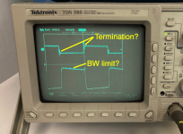
Thanks for that. This particular generator's output is marked as 600 ohms.I wonder if the ringing you're seeing is caused by improper termination of the signal generator. Signal generators often have 50 Ω output, so you need to terminate them in 50 Ω if you want a clean square wave. I also notice some sag on the flat parts of the square wave. That looks like a bandwidth limitation, but could be other things as well. I would expect the transformer to be able to pass 1 kHz square wave cleanly. You'll probably have some sag at 10 Hz.
Tom
When the 50k volume pot is dialed halfway, the load on the secondary looks like a voltage divider of 25k / 25k with a parallel load of 30k branching off that midpoint. I probably screwing this up 😉 but to me that looks like 25k ohms in series with 13.6k ohms (25k in parallel with 30k), or 38.6k ohms loading the secondary. Reflected back to the primary (1:8 turns) would be 603 ohms. Basically an exact match at the pot midpoint, right? The generator should be appropriately loaded I would think?
600 Ω output indicates to me that the signal generator is optimized for audio/telephony and not so much for RF performance. You can try terminating it with 600 Ω and see if you can get a clean square wave out of it.
I'm a little confused as to whether you're trying to build a preamp or just conducting a quick experiment. If the latter and you want 600 Ω at the input of the transformer, you need to present a secondary load of 600*N^2 = 600*64 = 38.4 kΩ. You can get there by turning the volume control to the max and adding a load of 165 kΩ on the output.
Tom
The ground lead of both oscilloscope probes was tied to the signal gen(single ended) ground and to pin 1 of XLR. And there is a cheater plug on the AC ground power input going into the scope? And both signals coming off opposite ends of a transformer winding are in phase? Is invert selected on either channels vertical input ?My oscilloscope readings were performed when XLR pin 1 was connected back to the signal generator's ground. As mentioned, this eliminated a distortion of low periodicity (possibly 60Hz) that was present when the oscilloscope probe ground leads were left floating.
Two equal resistors to ground?no way to generate a 0V ground reference on the secondary that I currently understand.
Well. I appreciate all the suggestions folks. Please forgive if my knowledge or understanding is lacking, I am learning.
I re-checked the device today- it's intended to be a passive preamp to convert unbalanced RCA to 'balanced' XLR, with a volume control in between. I should note that it works just fine driving my F1J or ACA, and sounds 'better' now that I've reversed the primary winding relative to the RCA input. Can confirm input to primary is now in phase with output to secondary.
On the scope, with a 1k sine wave, I noticed something striking. When the pot is turned below the midpoint, the + and - output of the secondary, as measured on XLR pins 2 and 3, respectively, are in phase. Their relative magnitude varies as a function of the pot. XLR pin 2 is connected to the wiper, and the + side output off the wiper shrinks in amplitude as the pot is dialed towards it's midpoint. At the midpoint, the + side wave is almost gone. Past the midpoint, the + side wave reappears and starts growing in amplitude but with inverted phase relative to the - output wave.
What I think this means is, the two ends of the secondary are in fact of opposite phase. Connecting them with a pot sums them, and at the point on the pot where the resistance on either side is equal, they sum to zero. As the wiper transits the pot, it transits this zero point, and the relative strength of signal changes from that of one side to the other, thus flipping phase. The summing to zero with resistances of equal value tied together at their ends is basically what PRR has been saying wrt generating a 0V relative ground point.
Now whether this is an appropriate circuit for a volume control in a passive preamp is another question. I have confirmed that it does in fact vary input volume to a power amp as expected, and it sounds pretty good to me, but the observation of phase shifting as a function of volume is unsettling. It doesn't seem desireable, and I have no idea what's going on in the amplifier under these conditions.
Putting the volume pot on the primary has concerned me due to the large turns ratio of this transformer and hence the relatively low impedance reflected to the primary from the amp loading the secondary. I have no idea what level of pot would be appropriate, nor what circuit topology for a volume control on the primary side would or should look like.
Link to a video showing the wave inversion as the wiper transits the pot.
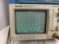
@tomchr these transformers as is do not pass a 1kHz square wave cleanly (see attached photo). There is clear ringing on the generator side from the primary (lower trace) which seems to be smoothed out on the secondary (upper trace). I suppose I could use my quasimodo rig to pick snubber values for the primary? Does that work for audio signals?
I re-checked the device today- it's intended to be a passive preamp to convert unbalanced RCA to 'balanced' XLR, with a volume control in between. I should note that it works just fine driving my F1J or ACA, and sounds 'better' now that I've reversed the primary winding relative to the RCA input. Can confirm input to primary is now in phase with output to secondary.
On the scope, with a 1k sine wave, I noticed something striking. When the pot is turned below the midpoint, the + and - output of the secondary, as measured on XLR pins 2 and 3, respectively, are in phase. Their relative magnitude varies as a function of the pot. XLR pin 2 is connected to the wiper, and the + side output off the wiper shrinks in amplitude as the pot is dialed towards it's midpoint. At the midpoint, the + side wave is almost gone. Past the midpoint, the + side wave reappears and starts growing in amplitude but with inverted phase relative to the - output wave.
What I think this means is, the two ends of the secondary are in fact of opposite phase. Connecting them with a pot sums them, and at the point on the pot where the resistance on either side is equal, they sum to zero. As the wiper transits the pot, it transits this zero point, and the relative strength of signal changes from that of one side to the other, thus flipping phase. The summing to zero with resistances of equal value tied together at their ends is basically what PRR has been saying wrt generating a 0V relative ground point.
Now whether this is an appropriate circuit for a volume control in a passive preamp is another question. I have confirmed that it does in fact vary input volume to a power amp as expected, and it sounds pretty good to me, but the observation of phase shifting as a function of volume is unsettling. It doesn't seem desireable, and I have no idea what's going on in the amplifier under these conditions.
Putting the volume pot on the primary has concerned me due to the large turns ratio of this transformer and hence the relatively low impedance reflected to the primary from the amp loading the secondary. I have no idea what level of pot would be appropriate, nor what circuit topology for a volume control on the primary side would or should look like.
Link to a video showing the wave inversion as the wiper transits the pot.
@tomchr these transformers as is do not pass a 1kHz square wave cleanly (see attached photo). There is clear ringing on the generator side from the primary (lower trace) which seems to be smoothed out on the secondary (upper trace). I suppose I could use my quasimodo rig to pick snubber values for the primary? Does that work for audio signals?
Attachments
It sounds like the scope doesn't know where ground is. If you have connected the ground lead of the probes to XLR pin 1, the secondary is floating relative to the scope, so you will get weird results. If you split the difference, say by adding two 10 kΩ in series across the secondary and using the centre between them as the 'ground' you'll likely see the two ends of the transformer are in opposite phase.
It's not clear which o'scope trace is which. Is the top trace the input and the bottom trace the output?
Do you see the excessive ringing if you connect one scope probe directly across the secondary (so the ground clip at one end and the probe tip at the other)?
Tom
It's not clear which o'scope trace is which. Is the top trace the input and the bottom trace the output?
Do you see the excessive ringing if you connect one scope probe directly across the secondary (so the ground clip at one end and the probe tip at the other)?
Tom
I would expect the two ends of the secondary to read opposite phase relative to a mimicked center tap. That result is consistent with my results and modeling of the behavior when there's an adjustable pot across the secondary. The challenge for me is where to put a volume pot, preferably on the secondary, in such a way that volume level adjustment doesn't disturb the relative phasing of + and -. It varies by position when the + output is taken off the wiper.It sounds like the scope doesn't know where ground is. If you have connected the ground lead of the probes to XLR pin 1, the secondary is floating relative to the scope, so you will get weird results. If you split the difference, say by adding two 10 kΩ in series across the secondary and using the centre between them as the 'ground' you'll likely see the two ends of the transformer are in opposite phase.
Top trace is the output on the secondary, bottom trace is off the primary. I know it's confusing, this top/bottom orientation wasn't planned.It's not clear which o'scope trace is which. Is the top trace the input and the bottom trace the output?
Edit: I didn't check a square wave on the secondary this way. Apologies.Do you see the excessive ringing if you connect one scope probe directly across the secondary (so the ground clip at one end and the probe tip at the other)?
Tom
Single pots are normally worked unbalanced. We can sometimes work a 1k pot in a balanced line without much strangeness. However 50k is IMHO too high to be wired balanced and get consistent results through the audio band. Putting the pot on your unbalanced side is natural. Make it as low resistance as your source can drive comfortably.
- Home
- Source & Line
- Analog Line Level
- Confirming balanced line level, little help?