2 Vrms actually means +/- 2.83 V peak, but still, +/- 5 V ought to do. The CS3310 datasheet says, "Signals approaching the analog supply voltages may be applied to the AIN pins if the internal attenuator limits the output signal to within 1.25 volts of the analog supply rails."
Are the opamps supplied with the same or do they get higher voltages? Mooly recently bumped into input common-mode range limitations when trying different opamps in a CDP-790, though since the circuit here has appreciable gain, only the limitations on the output side are of interest (along with common-mode distortion performance). Expect up to about +/- 4 V peak with the LME49710.
Since the CS3310 is not a low-noise king to begin with and has plenty of gain if needed, I would have liked to see lower gain and matched impedances at the opamp inputs as well. Try swapping R408 for a 3k3; the old 1k part can then replace R403. (A 250 ohm impedance imbalance is plenty good enough, and noise is not an issue.) Same goes for the other channel.
As far as the OPA(2)604 is concerned, I think Samuel Groner's measurements have shown pretty clearly that its area of expertise is higher than usual supply voltages (up to +/-24 V). It's pointless at +/-15 V, and pretty much useless at +/- 4.5 V (managing little more than 4.5 Vpp output even at no load).
I cannot pretend to understand all of what you wrote, but I truly wish that I did.
What I can confirm by looking at the schematic is that the pre-amp's opamps are supplied with +/-15v, as you can see here:
An externally hosted image should be here but it was not working when we last tested it.
I will spend some time trying to decipher the rest of what you have written.Thank you also for the resistor modification recommendation. Does it still apply now that you have seen the opamp power section?
P.S. Please also keep in mind that the CS3310 will be PGA2311 in short order...
P.P.S. I think Mooly's recommendation of 2604 was for my DAC, not the pre-amp being discussed. I should leave my DAC out of this conversation, for clarity. Apologies...
Last edited:
Since the CS3310 is not a low-noise king to begin with and has plenty of gain if needed, I would have liked to see lower gain and matched impedances at the opamp inputs as well.
I understand this point enough to comment... 😀
Indeed. In fact, in most cases the CS3310 (PGA2311) will in fact be acting as an attenuator 100% of the time. In other words, I suspect I will never have the volume control dialed to a state beyond 0 dB, as my power amp provides more power than my speakers can handle already.
For some reason I missed all these later posts. I mentioned the OPA2604 (OPA604 if you need the single version) because its one device I have used and one that I find does have certain charms. Its specified for use down to -/+4.5 volt supplies.
The relationship between peak, peak to peak and RMS is easy to get to grips with. If you draw a sine wave and put a line through the centre (the 0 volt reference), then it swings above and below that level. A CD player (DAC) has a typical maximum output of 2 volts RMS (the 0db level). On the sine wave that means the tips (top and bottom) reach a voltage of 2 (the RMS voltage) times root 2. So 2* √2 = 2.83 volts. That's the peak level the sine wave reaches at the top and at the bottom. The peak to peak level is just that multiplied by 2.
So the opamp needs to be powered from at least that voltage per rail plus a bit more to make up for the losses that occur internally in the circuitry.
Thanks for the explanation, Mooly. I understand.
sgrossklass, my PGA2311 arrives today and I think I will wait until I have installed and tested it before I do the recommended resistor swaps.
In the meantime, I have ordered some 22pF silver mica to install at C404 and C408. It seems to me that if they are in the schematic then they might just as well be installed and they might as well be high quality. If they reduce SQ, I can remove them and use them in another project.
Indeed. Typical modern (as in transistorized) power amps have an input sensitivity in the order of 1-1.5 V for full power, so basically the CS3310 by itself with its ~2.6 V max output and sizable amount of optional internal gain would do just fine. Granted, adding some external amplification may give even lower distortion and enables pointlessly high output levels that look good on paper even if they'll never be used, but noise is amplified as well, all of the time.Indeed. In fact, in most cases the CS3310 (PGA2311) will in fact be acting as an attenuator 100% of the time. In other words, I suspect I will never have the volume control dialed to a state beyond 0 dB, as my power amp provides more power than my speakers can handle already.
The PGA2311 should give a small improvement in noise over the CS3310, about 4.5 dB or so. Noise floor even at stock amplification should be quite acceptable then, and the gain reduction to 6 dB (3k3/3k3) should make it entirely inaudible.
C404/408 are not generally required. A cap in this position is typically used when amplifier input capacitance would result in high-frequency gain peaking, or just for bandwidth-limiting. I assume the former may have been the case with the AD797, which is an ultra low-noise part that has to have very low Rbb' (input transistor internal base resistance), therefore exposing input transistor parasitic capacitances.
Indeed. Typical modern (as in transistorized) power amps have an input sensitivity in the order of 1-1.5 V for full power, so basically the CS3310 by itself with its ~2.6 V max output and sizable amount of optional internal gain would do just fine. Granted, adding some external amplification may give even lower distortion and enables pointlessly high output levels that look good on paper even if they'll never be used, but noise is amplified as well, all of the time.
The PGA2311 should give a small improvement in noise over the CS3310, about 4.5 dB or so. Noise floor even at stock amplification should be quite acceptable then, and the gain reduction to 6 dB (3k3/3k3) should make it entirely inaudible.
C404/408 are not generally required. A cap in this position is typically used when amplifier input capacitance would result in high-frequency gain peaking, or just for bandwidth-limiting. I assume the former may have been the case with the AD797, which is an ultra low-noise part that has to have very low Rbb' (input transistor internal base resistance), therefore exposing input transistor parasitic capacitances.
Thank you. I feel as though I am really starting to grasp some of this stuff.
Will it do any harm to install C404/408? The reason I ask is because I may at some point opt to try different opamps (maybe including AD797). I am tempted to actually install DIP8 sockets there...
Perhaps the tweaker in me should leave well enough alone?
Oh, regarding the resistors; should I just stick with the stock quality SMD, or try to find something better?
(heading to the store to buy some much-needed soldering supplies for the PGA2311 transplant)
Last edited:
Well, with great effort, pateince and a bit of ingenuity, I got the PGA2311 installed yesterday.
Normally, it would require none of these attributes to install such a simple SMD device, however I had no flux (and neither did the local "electronics" store). To make matters worse, I have no hot air gun; just a 30w iron with a decently pointy tip.
Removing the CS3310 was a matter of heating each pin individually and using my smallest flathead micro driver to lift the pin off the board. I was not concerned about maintaining the functionality of the chip, so this worked out okay. After removing it, I used a macro camera lens (backwards) as a magnifying glass toinspect the pads and then added a tiny bit of solder to a few to fix them up.
The next challenge was to get the PGA2311 to sit still precisely where I needed it. I pressed a very small quantity of blue tack onto to board position and then aligned the chip and set in in place with moderate pressure. I then proceeded to spot solder each pin. Lighting was less than ideal, and I used my macro lens to constantly check my work.
First test; sound, but no volume control. Uh, ohh. Hmmm. Then I re-flowed all the pins on one side of the PGA2311 because some of them looked cold or just ugly. Second test; works perfectly.
Any of you real electronics people are probably reading this and either laughing or screaming at my hackery, but hey, it works!
It really does sound excellent now. I have not yet done a test to compare the sound to "direct source to amp" but I suspect the difference is negligible at this point.
Based on my experience with tiny SMD components (you just read it, in its entirety) I will be resisting the urge to perform the recommended resistor mods. For now. 🙂
I have reinstalled the components back into the chassis and closed it up for now. At some point it has to come back around to simply listening to the music. 🙂
Thanks to all who have offered help and advice.
Any of you real electronics people are probably reading this and either laughing or screaming at my hackery, but hey, it works!

Hey... I'm not laughing 😀
http://www.diyaudio.com/forums/parts/127924-working-smd-how-do-without-specialised-tools.html
Great to hear you got it installed OK.
Congratulations!!!🙂
Working with SMD is a ball of fun ain't it ?!!!!!! 😉
I actually found it easier to work with than I had anticipated.
Years ago I used to have a Copper C channels that I could bolt in to my soldering iron in place of the tip for removal of IC's and such.
I am thinking about making some kind of similar attachment for removal of those SMD passives and small semiconductors for reuse, from some of the other scrap boards that I have laying around.
Cheers!!!
jer 🙂
Last edited:
Reviving a very old thread… sorry about that.
I’ve got this Micromega Tempo amp with a CS3310 volume control. A DC swing from the previous stages fried up the chip. Yup, no coupling caps!
Since CS3310 is unavailable anywhere, except for fake ones from China which are cheap and aplenty, I was advised a so-called drop-in replacement, the PGA2311.
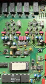
The 3310 draws its digital section + 5 V through a 22 Ω resistor (on the right) from the analogue + 5 V 7805.
The grounds are also common (same plane on PCB).
What do I do, considering that I can’t modify the PCB layout?
Will the PGA2311 work like that? I very much doubt it.
Cheers.
I’ve got this Micromega Tempo amp with a CS3310 volume control. A DC swing from the previous stages fried up the chip. Yup, no coupling caps!
Since CS3310 is unavailable anywhere, except for fake ones from China which are cheap and aplenty, I was advised a so-called drop-in replacement, the PGA2311.
The 3310 draws its digital section + 5 V through a 22 Ω resistor (on the right) from the analogue + 5 V 7805.
The grounds are also common (same plane on PCB).
What do I do, considering that I can’t modify the PCB layout?
Will the PGA2311 work like that? I very much doubt it.
Cheers.
Attachments
Last edited:
I can't answer the specifics so probably not much help but they look the same internally and what I read suggests they are replacements.
A drop in replacement should be just that. You will only know for sure by trying one.
I was advised a so-called drop-in replacement, the PGA2311.
A drop in replacement should be just that. You will only know for sure by trying one.

PGA2311 datasheet confirm It’s a drop in replacement parts for Cs3310.
https://www.ti.com/lit/ds/symlink/pga2311.pdf
so no worries
https://www.ti.com/lit/ds/symlink/pga2311.pdf
so no worries
Not a pinout issue of course.
I see that the +5 V (VD) is shared with the 3310 –only one 7805 – and is completely separate with the 2311.
The ground planes should be separate too, according to the sheet.
The old(er) 3310 seem to be less fussy.
This can apparently cause latching issues, potentially killing the chip in the second case.
I’ll go ahead anyway, we’ll see.
This is an example (Elektor). Below is the CS3319 application note.
I’ll go ahead anyway, we’ll see.
This is an example (Elektor). Below is the CS3319 application note.
I'm understanding you better now as to the problem 🙂
I think all you can reasonably do is try it and see. Perhaps 'issues' have arisen that are very application sensitive meaning that you may well not see a problem.
Hi,
Got the PGA2311. Not good. First of all, the chip doesn’t fit properly in a DIL16 socket, it’s slightly too small! Odd.
Then when volume is zeroed, music is heard nonetheless but totally muffled – I thought my tweeter was blown – and mute doesn’t work.
Got the PGA2311. Not good. First of all, the chip doesn’t fit properly in a DIL16 socket, it’s slightly too small! Odd.
Then when volume is zeroed, music is heard nonetheless but totally muffled – I thought my tweeter was blown – and mute doesn’t work.
By the way, the mute relay doesn’t operate with the replacement chip as it used to with the other one, even with the fried analogue section.
- Home
- Amplifiers
- Chip Amps
- Please help with opamp output stage