But is not the case for 12AX7, 12AU7, 6J1, 62N2 ect populary shown in internet sites with 12Volts of power supply.
..., how these circuits could works fine??
If it seems too good to be true, it probably isn't. You need to post the link to what you are seeing or add an attachment for the circuit because you may be misreading the circuit PS 12v source and not seeing what voltages are on the plate of the tubes. Or you are seeing some kid's toy version lab experiment.
oldjanus,
Referring to your Post # 13:
No . . . the tube curves do not show positive grid voltage.
No . . . the schematic does not show positive grid voltage, it has self bias which makes the grid more negative than the cathode.
The only positive grid voltage is Either if the tube is at zero bias and signal is applied,
Or, the signal goes more positive than the self bias voltage.
A 12AU7 is also specified for Oscillator service, and for Class C RF amplifier service.
In those modes, the grid is used with fairly large positive grid swings, and the grid current is rated for up to 10mA.
That is not Audio, unless you are building an Audio Oscillator, or a Guitar amplifier.
How about that?
To answer oldjanus yes it works but not great. I'm going to breadboard that circuit in post #13 (minus the mosfet) just to see what the THD really is.
You can make them 'work' at 12V, but it creates design difficulties and distortion will be high.But is not the case for 12AX7, 12AU7, 6J1, 62N2 ect populary shown in internet sites with 12Volts of power supply. These tubes was not designed to work with 12V of power supply, In fact there are not characteristics curves for that voltage level, then I keep my question, how these circuits could works fine??
http://valvewizard.co.uk/Triodes_at_low_voltages_Blencowe.pdf

really awesome!!!! tks a lot!You can make them 'work' at 12V, but it creates design difficulties and distortion will be high.
http://valvewizard.co.uk/Triodes_at_low_voltages_Blencowe.pdf
If it seems too good to be true, it probably isn't. You need to post the link to what you are seeing or add an attachment for the circuit because you may be misreading the circuit PS 12v source and not seeing what voltages are on the plate of the tubes. Or you are seeing some kid's toy version lab experiment.
as you can see the power supply voltage is 12V
Nobody going to comment on the plate load being something between 4.7k and 50k? Might as well leave it a question mark.
Thanks for the Schematic!
The LM317 requires a minimum 3V (In to out terminals), plus 1.25V across R4. That equals a total burden voltage of 4.125V, and it needs more than that voltage so that it can swing as the signal input swings in a negative direction. Give it 1V more so it can work with a 0.7Vrms.
5.125V.
What is the Threshold voltage of the IRF510 family of parts?
Perhaps 1.5V?
5.125V + 1.5V = 6.175V. The 12AU7 plate has to be at least at 6.625V.
With the 50k pot adjusted to its full range (50k):
12V - 6.175V = 5.375V across 50k.
5.375V/47k = 108uA
But how fast can 108uA slew the input capacitance of the IRF510 family of parts.
With a 4.7k resistor:
5.375V/4.7k = 1.14mA
12V - 6.175V = 5.825V. 5.825V/4.7k = 1.23ma
But, what 12AU7 can draw 1.23mA with the plate at 5.625V?
Be ready to select 12AU7 tubes.
Just my opinion
Last edited:
Ok I just put the tube portion together with a 4.7k plate load and 120R cathode resistor bypassed by 100uf. Grabbed some various 12AU7s from my bins and here we go. Input was 0.2v at 1khz and supply voltage 12.6v
Plate current varied between 300 and 700uA depending on the tube. A 47k plate load is unusable and this is the result.
So if you like low gain and distortion then this is the circuit to use.
| Ratheon | 0.8v out | 6.7% THD | |
| Mullard | 0.6v out | 4.1% THD | |
| Philips/ECG 5814 | 0.9v out | 1.9% THD | |
| RCA | 0.9v out | 1.9% THD | |
| Sylvania | 0.8v out | 2.7% THD |
Plate current varied between 300 and 700uA depending on the tube. A 47k plate load is unusable and this is the result.
So if you like low gain and distortion then this is the circuit to use.
Attachments
astouffer,
Thanks for doing the experiment!
What was your generator output impedance that drove the 12AU7 grid?
With 700uA and 120 Ohm self bias resistor, that is 0.084V self bias.
with 300uA and 120 Ohm self bias resistor, that is 0.036V self bias.
Generator:
0.2Vrms x 1.414 = 0.2828Vpeak.
There must have been grid current, because the self bias voltage was between 0.036V and 0.084V.
With 700uA of plate current, 4.7k plate load, and +12V B+:
4700 Ohms x 700uA = 3.29V across the 4.7k.
12V - 3.29V = 8.71V plate voltage. That is plenty of quiescent plate voltage to run the series IRF510 and LM317 circuit.
Now we know a lot about this circuit.
Simulation is one thing; but you did it with 5 Real World 12AU7 tubes.
Thanks again for doing that!
I noticed that the highest gain tubes had the lowest distortion, and the lower gain tubes had higher distortion.
astouffer,
Thanks for doing the experiment!
What was your generator output impedance that drove the 12AU7 grid?
I noticed that the highest gain tubes had the lowest distortion, and the lower gain tubes had higher distortion.
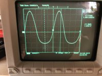
The generator was set to 50 ohms output and directly coupled to the grid. These tubes were all untested so some could simply be weak. That might account for the low gain/high distortion. In case anyone wonders the scope screenshot was reading 26% THD 🙂
astouffer,
I suspect that if you used a 1k resistor in series from the signal generator to the amp input, the 12AU7 grid current would make the distortion even higher, and the change in shape would be very easy to see, versus the scope photo in Post # 30.
I suspect that if you used a 1k resistor in series from the signal generator to the amp input, the 12AU7 grid current would make the distortion even higher, and the change in shape would be very easy to see, versus the scope photo in Post # 30.
Quoting OP:
'My question is: really with 12 volts is it possible to get a low distortion amplifier (and what is the applied concept), or in these amplifiers are the valves just "for decoration"?'
Should we expand the experiments to include other tubes/mosfets/schematics? It seems to me that the main question is about 12V B+, not specifically the 12AU7.
Original Post:
"My question is: really with 12 volts is it possible to get a low distortion amplifier (and what is the applied concept), or in these amplifiers are the valves just "for decoration"?" . . . "or in these amplifiers are the valves just "for decoration"?"
For low distortion using a vacuum tube in a circuit that only has 12V B+:
Either use a tube that is specifically made for low voltage operation, and get low distortion,
Or use a tube that is meant for 100V, 200V, 300V, and the distortion will be high.
An amplifier that uses higher voltage tubes with only 12V . . .
Ask the designer, marketeer, salesman, etc.
Or . . . Ask your self, "are they for decoration?" I think you know the answer.
All Generalizations Have Exceptions
Last edited:
But, what 12AU7 can draw 1.23mA with the plate at 5.625V?
Be ready to select 12AU7 tubes.
Just my opinion
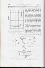
It's in the bottom corner square of the plate curve. No room to swing at all. 1v in can't get out. It would need 20v on the plate to stay out of cutoff. The gain if any is coming from the other gizmo plastic parts.
Last edited:
Has anyone characterized those low voltage car radio tubes? I have a suspicion that their distortion figures aren't great either. They were designed to drive germanium transistors in class B and none of those TO-36 package devices are not good above 5-10khz.
Last edited:
Has anyone characterized those low voltage car radio tubes? I have a suspicion that their distortion figures aren't great either. They were designed to drive germanium transistors in class B and none of those TO-36 package devices are good above 5-10khz.
I can't speak to much about how those tubes were deployed but in some radios there was a vibrator that developed an AC power signal to create stepped-up voltages above the 12v supply. If those vibrators are still available it would be cool to build something to demonstrate old school DC step-up techniques.
I actually repaired one of those vibrators in a Buick 52' many, many years ago. It used 6V6 for output. Crap, I still remember that.I can't speak to much about how those tubes were deployed but in some radios there was a vibrator that developed an AC power signal to create stepped-up voltages above the 12v supply. If those vibrators are still available it would be cool to build something to demonstrate old school DC step-up techniques.
- Home
- Amplifiers
- Tubes / Valves
- Minimum voltage for linear region of amplification