Hello all,
I have been working on building a pre amplifier with Ne5532, so I designed it in Multisim and everything worked OK.
After making the board and testing it with Rightmark Measurement software, it worked great until I noticed that when tone pots are positioned at center
every thing is ok and based on the design the mid band (800Hz) will not get affected by changing the pots position (Just like the result in Multisim),
but here the mid band is going to boost/cut between -/+ 4 dB with turning the pots to min or max. I checked the board and it seems to be ok.
I attached the schematic and frequency responses in deferent positions. Any thoughts or comments on this will be appreciated.
Alan.

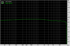
Response at center positioned pots:

Treble at max:

Bass & Treble at max:

I have been working on building a pre amplifier with Ne5532, so I designed it in Multisim and everything worked OK.
After making the board and testing it with Rightmark Measurement software, it worked great until I noticed that when tone pots are positioned at center
every thing is ok and based on the design the mid band (800Hz) will not get affected by changing the pots position (Just like the result in Multisim),
but here the mid band is going to boost/cut between -/+ 4 dB with turning the pots to min or max. I checked the board and it seems to be ok.
I attached the schematic and frequency responses in deferent positions. Any thoughts or comments on this will be appreciated.
Alan.
Response at center positioned pots:
Treble at max:
Bass & Treble at max:
Attachments
If you want the midband to be affected less by the tone pots, you need to move the bass action lower,
and the treble action higher.
So make the bass capacitor larger, and the treble capacitor smaller. Try doubling the 470nF bass capacitor
to 1uF, and halving the 10nF treble capacitor to 5nF..
and the treble action higher.
So make the bass capacitor larger, and the treble capacitor smaller. Try doubling the 470nF bass capacitor
to 1uF, and halving the 10nF treble capacitor to 5nF..
I will do that but do you have any idea why it is working in Multisim? (Consider the board and construction to be ok)

If you want the midband to be affected less by the tone pots, you need to move the bass action lower,
and the treble action higher.
So make the bass capacitor larger, and the treble capacitor smaller. Try doubling the 470nF bass capacitor
to 1uF, and halving the 10nF treble capacitor to 5nF..
This is the best advice. It will work better too. Most tone controls are centered around one frequency and that frequency is often 1 kHz.
The frequencies scale with the capacitor value. In other words C10 = 1uF means f3=400 Hz not 800 Hz. C11 = 5 nF means f3=1.6 kHz not 800 Hz. In practice this is more effective and less intrusive, in my opinion.
Exactly, the caps and other parts are the same as the schematic. just in practice everything moves -/+ 4dB up or downSo then in Multisim, the midband is still flat when the tone controls are turned up,
But not when you measure the actual circuit?
Have you measured the capacitor values that you are using?
Pots at center:So then in Multisim, the midband is still flat when the tone controls are turned up,
But not when you measure the actual circuit?
Have you measured the capacitor values that you are using?
Treble at max:
Bass % Treble at max:
As you can see in Multisim when you turn the pots the other frequency ranges stay the same, but in practice they move together , but the final result in reality is the frequency response that you would like, but between -/+ 4dB up or down depends on the pots positions.So then in Multisim, the midband is still flat when the tone controls are turned up,
But not when you measure the actual circuit?
Have you measured the capacitor values that you are using?
The tone control works fine actually, but the overall gain is going to change due to the changes of the pots. the whole response varies together .
So you suggest to choose higher value resistors and pots?The 5532 input impedance can be as low as 30k, so that could be a reason for the interaction.
That would be worse, and also increase the noise. A fet input op amp would be the way to improve that.
Moving the tone action farther from the midrange is the best option, and would also sound better.
Use high quality capacitors, since they are always working in the circuit, even when set flat.
Moving the tone action farther from the midrange is the best option, and would also sound better.
Use high quality capacitors, since they are always working in the circuit, even when set flat.
Thanks RaymaThat would be worse, and also increase the noise. A fet input op amp would be the way to improve that.
Moving the tone action farther from the midrange is the best option, and would also sound better.
Use high quality capacitors, since they are always working in the circuit, even when set flat.
I have been working on building a pre amplifier (tone control) design with Ne5532, so first I made it in Multisim and everything worked ok. After making the board and testing it with Rightmark Measurement software, it worked ok as the tone pots are positioned at center and based on the design the mid band ( around 800Hz) should not get affected by changing the pots position just like the result in Multisim.
Here on the bench not only the mid band, but the whole band is going to boost/ attenuation between -/+ 4 dB altogether as turning the pots to min or max. Beside this the circuit works just great and the final result in reality is the frequency response that you would like to have, but with -/+ 4dB boost or attenuation depends on the pots positions.
I attached the schematic and frequency responses in deferent positions. Any thoughts or comments on this will be appreciated.

Response at center positioned pots:

Treble at max:

Bass & Treble at max:

Response at center positioned pots🙁Multisim)

Treble at max🙁Multisim)

Bass & Treble at max: (Multisim)

Here on the bench not only the mid band, but the whole band is going to boost/ attenuation between -/+ 4 dB altogether as turning the pots to min or max. Beside this the circuit works just great and the final result in reality is the frequency response that you would like to have, but with -/+ 4dB boost or attenuation depends on the pots positions.
I attached the schematic and frequency responses in deferent positions. Any thoughts or comments on this will be appreciated.
Response at center positioned pots:
Treble at max:
Bass & Treble at max:
Response at center positioned pots🙁Multisim)
Treble at max🙁Multisim)
Bass & Treble at max: (Multisim)
But there are designs over the net with this opamp and also LM4562Try a fet input op amp instead.
Most do not care about the midrange interaction. If you do, you will have to move the bass hinge point lower,
and the treble hinge point higher. This is just a standard tone control, not an equalizer with high Q.
Circuits are not perfect, they can only do what you design them to do. In fact such a tone control when activated
will never reach 0dB in the midband, it just follows an asymptote, going closer but never reaching 0dB.
Thank you my friend, I appreciate it 🙂Yes, if the performance varies from the simulation, then the op amp model is bad or unrealistic.
- Home
- Source & Line
- Analog Line Level
- Help needed on Tone control section