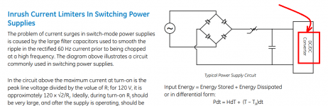
Looking at the datasheet for the CL series thermistors https://www.mouser.com/datasheet/2/18/AAS-920-325D-Thermometrics-NTC-Inrush-031814-web-1315885.pdf it shows the thermistor being placed between the rectifier and the filter cap. Is there any issue placing it in with the transformer primary?
This example answered my question. https://www.ametherm.com/blog/inrush-current/transformer-inrush-current-40va-transformer
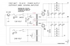
Here is the Power Supply schematic for the First Watt series of amplifiers designed by Nelson Pass. Did he place the inrush current limiting thermistor correctly? His schematic symbol for an inrush current thermistor is a resistor with an arrowhead and the label "TH".
_
_
Attachments
IMPORTANT: are you talking an SMPS (the HF transformer is irrelevant here, it´s after the switchers) or a conventional PSU, with a 50/60Hz iron transformers?Looking at the datasheet for the CL series thermistors https://www.mouser.com/datasheet/2/18/AAS-920-325D-Thermometrics-NTC-Inrush-031814-web-1315885.pdf it shows the thermistor being placed between the rectifier and the filter cap. Is there any issue placing it in with the transformer primary?
The example is for SMPS, you seem to be talking conventional, not the same thing AT ALL
EDIT: examples above are perfectly fine for SMPS, but it looks like you are talking THIS:
so please clarify.
They are calculated different.
EDIT 2:
yes, he´s talking 50/60Hz iron transformers here, not what astrouffer showed in the OP or your first answer.Did he place the inrush current limiting thermistor correctly?
Last edited:
All the applications I have seen for limiting in-rush current to a large power supply transformer is in the primary AC lines. Makes sense since the transformer is where it all starts, and it will help protect the power switch.
- Home
- Amplifiers
- Power Supplies
- Inrush thermistor placement