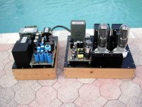
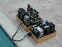
I almost completed a single ended KT88 amp. It worked fine, but I did not finish it because it weighs 30kg. I put all high voltage tube amps high up on a shelf to keep them away from children. The shelf is only rated for 30kg so I can't put it up there. Even if I wanted to put it up there I don't have the strength to safely lift it that high. So the amp is just sitting there and I can't use it. The only options is to build a cage around it or to split it into 2 chassis. I am choosing the later.
It is definitely not ideal, but occasionally I read some of you do this. What do you use for the connection between them. The easiest option I came across is the MC4 connectors meant for solar panel. They are rated from 1500V DC 30A. I wonder if anyone have experience using them?
My other option is to use octal CMC type tube socket (the bottom can be plugged into any tube socket) which would require a bit more work. My other other option is to make both sides unremovable without opening up the chassis,
On tne commercial side, I see manufacturers use aerospace connectors for this. The highest rating I found are at 600V. Not unusable, but I would prefer the rating to be 800V or higher.
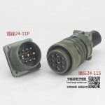
I have used, and prefer MS style connectors. They're rugged, reliable and have interchangeable inserts. I like at least a size 18 (middle number) which is about one inch in diameter. If more then four or five pins a larger size is better so you can double up on pins for filaments, assuming you have a large enough chassis. Yea, they're somewhat expensive but if you search around they do show up like the one shown.
Pictured is a size 24 that's around 1½ dia. (The last number represents the "pin configuration" and not the actual number of pins.)
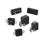
I've also used Cinch Jones connectors. They are cheaper and perhaps easier to find from supply houses and sellers on line. The only down side is that they can pull apart more readily. Although they can be bought with locking clamps that prevents that. You should always orient any connectors with the pins on receiving side and the socket on source side so voltages are shielded when not connected.
Pictured is a size 24 that's around 1½ dia. (The last number represents the "pin configuration" and not the actual number of pins.)
I've also used Cinch Jones connectors. They are cheaper and perhaps easier to find from supply houses and sellers on line. The only down side is that they can pull apart more readily. Although they can be bought with locking clamps that prevents that. You should always orient any connectors with the pins on receiving side and the socket on source side so voltages are shielded when not connected.
Attachments

You could go with the MHV or SHV connectors. They look like a BNC but with extra insulation and rated for kilovolts. The nice part is being able to buy ready made cables.
I don't know if these will meet your needs but I've used this size as well as the 28 series.
Connectors
.jpg")
Connectors
Thanks for your inputs. 🙂
FWIW my amp HV is around 420V under normal condition. Unloaded it can go up to 680V. I have also soft start and delay.
Those MS connectors, or similar, from all the datasheets that I have came across, the highest maximum working voltage I have seen is 500V, and can withstand 1500V for 2 minutes. Have you come across higher ones? Although in practice it probably will work fine.
Some have reported IEC connectors works fine too despite being usually rated 250V.
The SHVs are rated for 5000V. To my untrained eyes they don't look better insulated than the MS. The MC4 connectors rated at 1500V looks kinda thin to me. That said they are all single connector connections.
I usually used similar (soviet) military connectors for 600V:
https://www.ebay.com/itm/2541966200...PvVuS1bEPSlr090us14R5zazhe|tkp:Bk9SR5jiiNveYA
https://www.ebay.com/itm/2541966200...PvVuS1bEPSlr090us14R5zazhe|tkp:Bk9SR5jiiNveYA
Wow Euro, that's a good price! And NB remember to keep at least one (or more) filter capacitors in the main amplifier chassis and not make the signal return back through the connecting cable. And with that many pins you can remove some to improve voltage resistance between them.
I've used GX16 with 700V (unloaded) and for -110V and 560V in the same connector:
https://www.ebay.com/itm/125185743994
https://www.ebay.com/itm/125185743994
It depends on how you feel about ergonomics/convenience. I've taken to using high voltage (18KV) wire from board to board . No plugs to fiddle with on the outside of the chassis.
Phoenix contact for one makes wire to board connectors that are rated fairly high. Get a connector with more positions than you need and leave appropriate ones unused as spacers between those with high voltage differentials.
Here's one of many different types.
The downside is that for conventional chassis to disconnect you have to open one up to loosen off or unplug the connections but not a problem if you make the chassis with that in mind.
Harting also makes quite a few non-mil panel mount connectors that are rated for >1KV high voltage but they're a pain to search as those numbers are not shown on the vendor's page. You have to open up the individual datasheets or look through the manufacturer's main catalogs.
I have some NOS military spec connectors if your in the UK that may do the job. Like these for the heaters - https://www.lmslichfieldltd.com/epages/BT4011.sf/en_GB/?ObjectPath=/Shops/BT4011/Products/Lms0190B & these for g2 supply,bias etc - https://www.lmslichfieldltd.com/epages/BT4011.sf/en_GB/?ObjectPath=/Shops/BT4011/Products/"top shed 174D" . For my last amp which is similar to yours I used these for every rail up the 350v, for the 500v rail I used SO230/PL259 connectors.
Andy.
Andy.
Last edited:
I have used the Cinch Jones connectors seen in the second picture from post #2 in my dual chassis designs. I put the positive HV connection in a corner pin and left the two adjacent pins unconnected. My amp runs at 1050 volts when operational and well over 1100 when unloaded. The amp has existed for almost 20 years but does not see use today due to curious grandkids and exposed tube sockets for the 845 tubes.
Attachments
- Home
- Amplifiers
- Tubes / Valves
- External power supply connectors