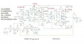
next (planned) design option Fury SE, peculiarities :
the input stage gain is standard from Fury with a gain of 76db open loop,
the second gain stage is already 50dB open loop,
the repeater for the output transistors has become a push-pull driver.
Power Supply increased to +/- 40 volts. Distortion is much less than 0.001% even at maximum power. All simulation data in attachment. All voltage amplifier blocks are working, as they previously had a practical implementation, the output stage with the driver has been updated and has not yet been done in practice.
Attachments
Last edited:
A variant with the Fury ideology without the use of JFET transistors at the input, that is, the gain driver is implemented only on bipolar transistors.
Q2 and Q5 require small heatsinks on the board. Q9 and M1 are best placed on the main radiator where the output transistors are.
Q10 is a thermostabilizing element of the multiplier, located next to the output transistor.
X1 - servo to stabilize the operating point at the output.
Supply voltage is now +/-50V
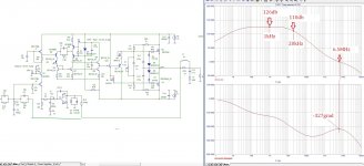
Due to the simplification for the output stage, the voltage amplifier driver is loaded on the high capacitance of the mosfet output transistors, which is why after 1 kHz (95 dB) the gain without negative feedback has a decline and at a frequency of 20 kHz is 73 dB.
Distortion at an output power of 100 watts into a load of 4 ohms is 0.002% (1kHz).
Distortion at an output power of 100 watts into 4 ohms at a frequency of 20 kHz is 0.012%
Сorrection is taken completely from the previous versions of Fury.
Q2 and Q5 require small heatsinks on the board. Q9 and M1 are best placed on the main radiator where the output transistors are.
Q10 is a thermostabilizing element of the multiplier, located next to the output transistor.
X1 - servo to stabilize the operating point at the output.
Supply voltage is now +/-50V
Due to the simplification for the output stage, the voltage amplifier driver is loaded on the high capacitance of the mosfet output transistors, which is why after 1 kHz (95 dB) the gain without negative feedback has a decline and at a frequency of 20 kHz is 73 dB.
Distortion at an output power of 100 watts into a load of 4 ohms is 0.002% (1kHz).
Distortion at an output power of 100 watts into 4 ohms at a frequency of 20 kHz is 0.012%
Сorrection is taken completely from the previous versions of Fury.
Attachments
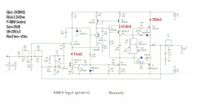
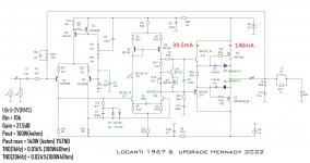
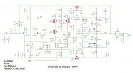
I tried to universalize the 1967 UN Lokanti circuit by adding cascades that make the parameters independent of power stability, in the original this dependence is, to put it simply, in the original it was necessary to use stabilized power for voltage amplifier, in the circuit below this is no longer necessary ...
gain without NFB increased to 76.5dB (1kHz) at 20kHz - 69db, pole 8kHz, Fed=2MHz, margin of stability 60degrees
driver current Q11Q12 39.5mA
mosfet output current 140mA (current regulated by R18)
X1 regulates 0 output
R20 removes overcompensation in the multiplier Q10
the correction is progressive according to the idea of Lokanti 1967, but recorrected for the new elemental base...
Added boost capacitor C6
Added D1D2 anti-clip chain,
power supply +/-45 volts not stabilized.
Gain=21.5dB
Attachments


Interesting scheme. Source resistors on the output are not needed?I tried to universalize the 1967 UN Lokanti circuit
Substitute models BD139 and BD140 from B. Cordell, as they are not quite accurate in the Microcap library.
http://www.cordellaudio.com/book/spice_models.shtml
Last edited:
Interesting scheme
Thanks
no, not needed, even if you want to put two pairs of output mosfetsSource resistors on the output are not needed?
for 10 years of modeling and practical implementations, so far the existing models have never failed...Substitute models BD139 and BD140 from B. Cordell, as they are not quite accurate in the Microcap library.
Very nice implementation! I see a lot of progress over the years, well done.I tried to universalize the 1967 UN Lokanti circuit by adding cascades that make the parameters independent of power stability, in the original this dependence is, to put it simply, in the original it was necessary to use stabilized power for voltage amplifier, in the circuit below this is no longer necessary ...
gain without NFB increased to 76.5dB (1kHz) at 20kHz - 69db, pole 8kHz, Fed=2MHz, margin of stability 60degrees
driver current Q11Q12 39.5mA
mosfet output current 140mA (current regulated by R18)
X1 regulates 0 output
R20 removes overcompensation in the multiplier Q10
the correction is progressive according to the idea of Lokanti 1967, but recorrected for the new elemental base...
Added boost capacitor C6
Added D1D2 anti-clip chain,
power supply +/-45 volts not stabilized.
Gain=21.5dB
I have a few questions if I may. In the schematic attached called 'Locanti' I don't see the Locanthi circuit. Maybe the name is from a previous version?
Also, you present many simulation results, did you do any measurements on THD for instance?
Jan
Hello!Very nice implementation! I see a lot of progress over the years, well done.
thanks for the comment, it's very nice!
Perhaps you mean that the name Lokanti is more associated with the triple (T) in the output stage, but there are several nuances, I think that the deuce with output transistors on power mosfets is similar to the trio on bipolars, in 1967 it was probably problematic to make the output stage on mosfets, and it seems that in 10-15 years it became possible. The second point is a voltage amplifier in series connection of two differential stages of different conductivity, where the B-E transition of the input transistor of the differential stage is covered by a negative feedback, in addition to everything else, with progressive correction. I have not seen this in similar cascades either with Flickinger or Holton.In the schematic attached called 'Locanti' I don't see the Locanthi circuit.
no problemMaybe the name is from a previous version?
yes, only Fury the first option was measured, which showed less than 0.001% distortion.Also, you present many simulation results, did you do any measurements on THD for instance?
The rest are not, only simulation in models, Fury II was made in one copy, which was immediately taken away after listening.
The Fury three have been taken by audiophiles to work with tube amps, with Fury replacing the Class A amp both times at JLH 2005's and Aleph Pass.
Henk.
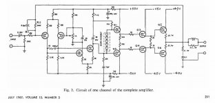
I don't think it is fair to call anything a Locanthi what isn't. The specific Locanthi Triple was clearly described by Mr. Locanthi, as shown in the patent.
The circuits you showed are not. Your circuit has value on itself and it is very worthwhile, you do not need to associate yourself with someone else based on incorrect terminology to look better.
You are better than that.
https://patents.google.com/patent/US3428908
Jan
The circuits you showed are not. Your circuit has value on itself and it is very worthwhile, you do not need to associate yourself with someone else based on incorrect terminology to look better.
You are better than that.
https://patents.google.com/patent/US3428908
Jan
Attachments
Last edited:
I understand, thanks.Your circuit has value on itself and it is very worthwhile, you do not need to associate yourself with someone else based on incorrect terminology to look better.
You are better than that.
Henk.
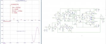
A variant of the amplifier with a paraphase control of the output transistors mosfet in class AB.
amplifiers with such a topology are rare, but it has a very interesting and probably even musical sound, because. at the output, mosfets of the same type of conductivity are used, and therefore with equal parameters.
The amplifier uses in-phase stabilization of the quiescent current on the transistor Q2.
X1 adjusts the bias of the output transistors.
X2 adjusts zero at the output of the amplifier.
Q5 unloads Q4 in terms of power, and Q9 unloads Q10. The circuit uses progressive correction with anti-clip diodes d1d2, The NFB depth is 51dB (2Hz....20kHz).
Attachments
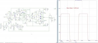
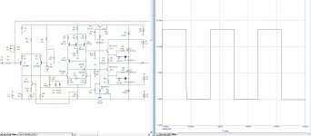
SR=8,5V/uSHennady, what is the simulated speed (slew rate) of this amp?
For comparison, the slew rate of a JLH 2005 Class A amplifier is only 4.5V/µS.This topology tends to be slow...
P.S. also posted a constraint which is symmetrical.
Attachments
Last edited:
Yeah, this is very slow...
in itself, this speed is not the only criterion for evaluating the sound quality of an amplifier.
The slew rate value of the amplifier itself is necessary to understand the matching of the pre-amplifier and the power amplifier. If we take the ratio that was proposed by Walter Jung back in 1997, then we get that for an amplifier with a lower slew rate, a more powerful driver is needed before the power amplifier, and that's all ...
Everything else is an invention of what is not related to the quality of sound reproduction. but it has more to do with digital technology, from where the concept of slew rate was borrowed.
To make sure that this is the case, it is enough to test the amplifier at a nominal input voltage at a frequency of 100 kHz,
for an amplifier with a lower slew rate, the amount of distortion will increase linearly, i.e. proportional to the increase in frequency relative to 20 kHz. With a higher speed, the graph of this dependence has a smaller slope...
Last edited:
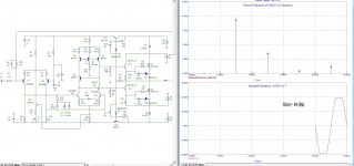
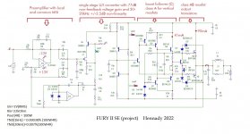
The Fury 2SEversion differs from the original Fury 2 version by the presence of a bipolar power amplifier supply and a modified boost follower for the output vertical mosfets. A boost follower is needed to pump the input capacitances of the output transistors of the mosfets.
a simple dual TL072AC chip is used at the input, 1 part of which is a preamplifier, and 2 part is a servo to maintain 0 at the output, because circuits with Jfet at the input are not able to stabilize the voltage at the output of the amplifier for a large signal.
All blocks had a practical implementation and high-quality sound. Distortion spectrum is very very short - only the second harmonic.
other explanations in the attachment.
Attachments


The mosfet is a very interesting output device.
You can make it sound like a tube amplifier depending on how you switch it.
In class D we go hard but at a very high frequency say 500kHz.
In class A we want it tubey.
In class AB we want to fake class A.
Also look at these amplifiers while working with mosfets
https://firstwatt.com/pdf/prod_f5_man.pdf
https://www.passdiy.com/project/articles/burning-amplifier-1
https://www.passdiy.com/project/articles/burning-amplifier-2
https://www.firstwatt.com/pdf/art_mos_citation.pdf
FWIW there's a ton of GitHub projects of kicad adapters for all shapes and sizes. Panelize them with your next board order. Amazon sell mixed packs, they're pretty cheap.Don't tell me about surface mount parts. SM adapters are $8 each if I don't send my debit card # to the orient for hacking.
philosophy.)))The mosfet is a very interesting output device.
You can make it sound like a tube amplifier depending on how you switch it.
I saw this a long time ago, why is this here?Also look at these amplifiers while working with mosfets
How do these links help you build an amplifier?
- Home
- Amplifiers
- Solid State
- FURY amplifier