A bandpass filter on the midrange would give better results.
The idea is to filter off the high frequencies in addition to the low frequencies, allowing the midrange driver to reproduce only the midband frequencies and not overlap with the tweeter.
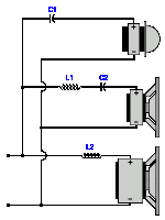
A bandpass filter consists of an inductor in series with a capacitor, as shown in the attached schematic.
(The inductor in series with the woofer is optional.)
Attachments
Last edited:
I found some nice XO and wiring pictures on the web for comparison, especially on this site:
https://www.audiovintage.fr/leforum/viewtopic.php?t=27809
So far I cant find and error in your XO.
On picture at #4 amp plus/minus should go other way around, but that dont affect operation. Cap replacement job looks ok.
Possible reason why mid isnt working may be faulty 1,7 Ohm resistor or poor solder joint. Have you tried to check it, and do you have that problem on both speakers?
Btw, that 1,7 Ohm goes in series with midrange, so if replacement driver is 4 instead of 8 Ohm you can simply replace it with somewhat higher value, say 3-4 Ohms.
Iam working on schematics drawing, a bit weird layout but not to hard to understand. Hope to post some tomorrow.
Also, found this test from HiFi Stereo
https://www.audioservicemanuals.com/s/scott/scott-s15/70397-scott-s15-test
No schematics, but some nice additional data that might help.
@Davor D one of those pictures was very helpful, thanks, we can cross-check.

You were right of course if as I suspect you were talking about a series crossover... (a way to do a lot with few parts)Yeah, started to do a ladder scheme,

Last edited:
I agree with schematics from #43, but I think "H" terminal (also connected to center of other connector) should be amp+
That HiFi Stereo article also claims that.
This is hand sketch I made. On available pictures I couldnt see the value of tweeter series capacitor so I left it without value. Interesting layout anyway.

That HiFi Stereo article also claims that.
This is hand sketch I made. On available pictures I couldnt see the value of tweeter series capacitor so I left it without value. Interesting layout anyway.
I agree it looks upside down. 🙃should be amp+
Because it is 4 ohms? No, don't do that.does it make sense now to add a 3-4 ohm series resistance to the mid?
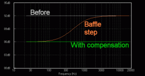
By the way, have you used VC to sim your baffle? It will make more than a few dB difference.
I agree it looks upside down. 🙃
Its good to have drawings from both ends, your version is a bit more revealing.
Last edited:
So, I'd like to ask again Galu's question, as I fear it got lost in the series of answers: does it make sense now to add a 3-4 ohm series resistance to the mid?
To revisit your question which refers to a simple crossover for your three, non-original, replacement drivers:
If the midrange is too loud then put a resistor of an appropriate value in series as described earlier (post #15). Same goes for the tweeter.
Last edited:
Understood, thanks for the clarifications.
@AllenB : I'm very new to all this, could you explain a bit further what you meant when you asked whether I have you used VC to sim your baffle?
I was about to send a new frequency graph obtained playing around with VituixCAD, but with your comment I fear there is something very basic that I missed.
Are you simulating using factory data and are you planning on measuring instead? There will be differences. One is due to the outside of your box not being able to support all frequencies the same and it affects how you set them up when you cross.
It's OK to start with factory plots as long as you do something about the difference or at least keep it in mind.

It's OK to start with factory plots as long as you do something about the difference or at least keep it in mind.

I do the simulation with files I found either on this forum or on dibirama.altervista.org. I'll have to look more into the baffle step then.
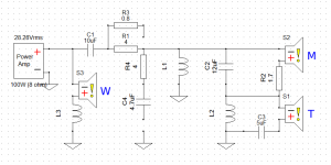
In the meantime, I played some more with VituixCAD, and simulated a 2nd Order Reverse Polarity XO. Here is how it looks. What do you guys think? I'd love to have your opinions before putting together something silly. Also, I'm surprised to see the medium with upside down polarity in such XO. The driver won't play inside-out, right?! I guess it would make sense if I had a clue about engineering.

All the best,
Eli
In the meantime, I played some more with VituixCAD, and simulated a 2nd Order Reverse Polarity XO. Here is how it looks. What do you guys think? I'd love to have your opinions before putting together something silly. Also, I'm surprised to see the medium with upside down polarity in such XO. The driver won't play inside-out, right?! I guess it would make sense if I had a clue about engineering.
All the best,
Eli
The midrange is reverse wired in your circuit to ensure it is acoustically in phase with the other drivers.
That is what the term "Reverse Polarity" is indicating.
That is what the term "Reverse Polarity" is indicating.
By all means try it. I suspect you'll want to bring the midrange down a little and the treble even more.
Edit: Make sure the impedance looks usable.
Edit: Make sure the impedance looks usable.
OK! So I am not sure I have fully understood the dos and don't of the impedence graph. So here it (with all other graphs, on an updated version, which also uses the exact values of components found at my local dealer)

...sorry, I see that I failed to send the end of my message in the last post. So here is the state of things now. Would you say that the impedance is usable? Your opinion on this (or any part of this XO) is much appreciated!
The lowest point is higher than 5 ohms. That was the concern, so that looks OK.
Try taking the resistor away from the woofer circuit. In any case let it be higher in level.
Try taking the resistor away from the woofer circuit. In any case let it be higher in level.
- Home
- Design & Build
- Construction Tips
- Revamping Scott S-15 speakers
