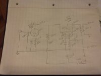
Hello All,
I breadboarded another amp this weekend and have been trying to figure out how my operating conditions are on the 6f5 driving the 2a3. I get lost when I try to draw the ac load line. I know the 6f5 is not a preferred tube to drive a 2a3 but it does sound good at low to medium volume which is a lot with my 100+ decibel speakers. Any comments on the operating points of the 6f5 or the circuit as a whole.
O.B.

Member
Joined 2009
Paid Member
Good choice of tube, it’s been used before like this, trying to remember who it was - maybe Dennis Fraker?
I’d suggest you are already at a good operating point. I do think you have your units of current incorrect, it’s either 0.65mA or 0.00065A
I’d suggest you are already at a good operating point. I do think you have your units of current incorrect, it’s either 0.65mA or 0.00065A
Don Garber used the 6SF5, which has the same specs but in an octal base with no grid cap.Good choice of tube, it’s been used before like this, trying to remember who it was - maybe Dennis Fraker?
...
The operating points look quite reasonable. At start-up, the 2A3 grid can see a high voltage as it warms up, which can cause arcing. Solutions are an indirectly heated rectifier tube, or a 2a3 grid to cathode diode.
I have used the 6K5 to drive a 2A3 insted of the 6F5. The results are good, but ultimately the sound is a bit "polite" with compressed dynamics. Here is 6K5 operating point that has more current through the tube than the 6F5 that you can try. With a mu of 73 and a bias voltage of -2V you should easily be able to drive the 2A3 or even a 300B to full output. I used a plate supply of 390V which should conform to your power supply.
Attachments
Thanks Bigun, Paul and Palustris for the replies.
I am using a 5v4ga for a slower warm up. I will try a 6k5g as well as it looks like I can tie pins 3 and 4 together, change the 330k plate resistor to 100k and maybe lower the drivers tube cathode resistor a little to bias it. Correct?
Why is it when I measure the plate of the 6f5 (172) and the cathode of the 2a3 (221) and subtract it from the plate it calculates out to 49V. But when I place the meter probes on the 6f5 plate and 2a3 cathode at the same time it reads 45.8 diff voltage.
Which one do you go by?
Thanks again Guys!!!
Meter loading. What is your meter impedance? What do you calculate when you put that in the circuit where the meter is probing? (But anyway, all tube-work is +/-20% precision because tubes vary that much or more.)when I measure the plate of the 6f5 (172) and the cathode of the 2a3 (221) and subtract it from the plate it calculates out to 49V. But when I place the meter probes on the 6f5 plate and 2a3 cathode at the same time it reads 45.8 diff voltage.
Your numbers are wrong. You figured Amps but wrote mA. Checking and ignoring that:figure out how my operating conditions
Note that the plate circuit impedance is around 50k||330k or 42k. 250pFd of grid circuit capacitance is a 20kHz pole. Ah, 2A3 may be under 100pFd, so 50kHz @-3dB, 25kHz@-1dB, not too bad. (But even Leo Fender would run more driver current.)
Cathode of the diode goes to the cathode of the tube, so it only conducts when the grid goes positive WRT the tube cathode.@Paul Joppa, Am I correct in thinking that the negative side of the diode goes to the grid? Bill
(In my opinion, cathode and anode are more reliable terms that positive and negative for diodes.)
- Home
- Amplifiers
- Tubes / Valves
- 6F5 operating points.

